
Shipping (Fishing
Vessels of 24 Metres in Length and Over) (Safety Provisions) (Jersey)
Order 2004[1]
PART 1
PRELIMINARY
1 Interpretation
In this Order, unless the context otherwise requires –
“ ‘A’ class division” means a bulkhead
or part of a deck which is –
(a) constructed
of steel or other equivalent material;
(b) suitably
stiffened;
(c) so
constructed as to be capable of preventing the passage of smoke and flame to
the end of the 60 minute standard fire test; and
(d) so
insulated where necessary with suitable non-combustible materials such that, if
the division is exposed to the standard fire test, the average temperature of
the unexposed side of the division will rise not more than 139°C above the
initial temperature nor will the temperature at any one point, including any
joint, rise more than 180°C above the initial temperature within the time
listed below:
|
A - 60 standard...................................................
|
60 minutes
|
|
A - 0 standard.....................................................
|
0 minutes
|
“ ‘B’ class divisions” means those divisions
formed by bulkheads, decks, ceilings or linings which –
(a) are
so constructed as to be capable of preventing the passage of flame to the end
of the first 30 minutes of the standard fire test;
(b) have
an insulation value such that during the standard fire test the average
temperature of the unexposed side will not rise more than 140°C above its
initial temperature, nor will its temperature at any one point, including any
joint, rise more than 225°C above its initial temperature within the time
listed below:
|
B - 30 standard...................................................
|
30 minutes
|
|
B - 15 standard...................................................
|
15 minutes
|
|
B - 0 standard.....................................................
|
0 minutes
|
(c) except
in the case of divisions constructed of glass reinforced plastic, are
constructed of suitable non-combustible materials and their supporting members
or structures are also constructed of non-combustible materials;
“accommodation spaces” means corridors, lavatories,
cabins, offices, crew spaces, isolated pantries and similar spaces;
“breadth of a vessel” means the maximum width measured –
(a) to
the moulded line of the frame of a vessel with a metal shell;
(b) to
the outer surface of the hull of a vessel with a shell of any other material or
of a composite vessel;
“any ship or boat, or any other description of vessel used in
navigation; Class C boat” means a boat complying with the provisions of Article 85;
“collision orders” means international collision
orders relating to the avoidance of
collisions between ship that apply to Jersey ships;
“control stations” means spaces in which main navigating
or radio or central fire recording equipment or an emergency generator are
located;
“crew space” includes sleeping rooms, mess rooms,
sanitary accommodation, hospital accommodation, recreation accommodation, store
rooms and catering accommodation provided for the use of seamen but does not
include any accommodation which is also used by or provided for the use of
passengers;
“dead ship condition” means a condition where no power
is available in the vessel;
“distant water voyage” means a voyage during the course
of which a vessel proceeds outside the area bounded by lines adjoining the
following positions –
(a) coast
of Norway at 65° 00’N;
(b) 65°
00’N 8° 00’E;
(c) 61°
30’N 18° 00’W;
(d) 43°
00’N 18° 00’W;
(e) coast
of Spain at 43° 00’N;
“draught” means the vertical distance from the moulded
base line amid-ships to the operating water line of a vessel;
“enclosed superstructure” means a superstructure with –
(a) enclosing
bulkheads of efficient construction;
(b) access
openings, if any, in those bulkheads fitted with permanently attached
weathertight doors of a strength equivalent to the unpierced structure which
can be operated from either side; and
(c) other
openings in sides or ends of the superstructure fitted with efficient
weathertight means of closing, but does not include a bridge or poop unless
access is provided for the crew to reach machinery and other working spaces
inside the bridge or poop by alternative means which are available at all times
when bulkhead openings are closed;
“equivalent material” where the words are used in the
expression “steel or other equivalent material” means any material
which, by itself or due to insulation provided, has structural and integrity
properties equivalent to steel at the end of the standard fire test;
“fishing vessel” means a vessel which is for the time
being used for or in connection with sea fishing but does not mean a vessel
used for fishing otherwise than for profit;
“freeboard deck” means the uppermost complete deck
exposed to the weather and sea which has permanent means of closing all
openings in the weather portions thereof and below which all openings in the
sides of the vessel are fitted with permanent means of closing watertight. In a
vessel having a discontinuous freeboard deck, the lowest line of the exposed
deck and the continuation of that line parallel to the upper part of the deck
is to be taken as the freeboard deck.
A lower deck may be designated as the freeboard deck subject to its
being a complete and permanent deck continuous both –
(a) in a
fore and aft direction at least between the machinery spaces and peak bulkheads;
and
(b) athwart-ships.
When this lower deck is stepped, the lowest line of the deck and the
continuation of that line parallel to the upper part of the deck is to be taken
as the freeboard deck. When a lower deck is designated as the freeboard deck,
that part of the hull which extends above the freeboard is treated as
superstructure;
“height” in relation to a superstructure or other
erection means the least vertical distance measured at side from the top of the
deck beams of a superstructure or an erection to the top of the freeboard deck
beams;
“independent power pump” means a pump operated by power
otherwise than from the vessel’s main engines;
“inflatable boat” means a boat complying with Article 86;
“launching appliance” means the appliance complying with
Article 100;
“length” in relation to a vessel, means the length shown
on the vessel’s register and the “length overall” of a
fishing vessel shall be determined in accordance with the Tonnage Regulations;
“lifeboat” means a boat complying with Article 84;
“liferaft” means a liferaft complying with Article 87;
“machinery control room” means a room from which the propelling
machinery and boilers serving the needs of propulsion may be controlled;
“machinery space” in relation to vessels of 24 metres in
length and over means any space used for propelling, auxiliary or refrigerating
machinery, boilers, liver boilers, fish meal plant, pumps, engineers’
workshops, generators, ventilation or air conditioning machinery, oil filling
stations and similar spaces and trunkways to such spaces;
“main circulating pump” means the pump installed for
circulating water through the main condenser in steam driven vessels or the
pump which circulates the main engine sea water coolant in motor driven
vessels;
“maximum service speed” means the greatest speed which
the vessel is designed to maintain at sea at her deepest seagoing draught;
“motor lifeboat” means a lifeboat complying with Article 84(5);
“navigable speed” means the minimum ahead speed at which
the vessel can be effectively steered;
“non-combustible material” means a material which when
heated to a temperature of 750°C neither flames for longer than
10 seconds duration nor raises its internal temperature or the temperature
of the test furnace more than 50°C above 750°C when tested in
accordance with British Standard Specification 476; Part 4; 1970 and
the expression “combustible material” shall be construed
accordingly;
“oil fired boiler” means any boiler wholly or partly
fired by liquid fuel not being a domestic boiler of less than
73.28 kilowatts;
“oil fuel unit” means the equipment used for the
preparation of oil fuel for delivery to the oil burners of an oil-fired boiler
or that used to prepare heated oil for delivery to an internal combustion
engine and includes the oil pressure pumps, filters and heaters;
“person” means a person over the age of one year;
“principal length” means the length measured in metres
on a straight line from the fore part of the stem at top to the aftermost side
of the transom or stern contour;
“principal breadth” means the maximum breadth measured
in metres on a straight line to the outside of the frame lines of a vessel the
hull of which is constructed of metal or to the outer surfaces of a vessel the
hull of which is constructed of other material;
“principal depth” means the depth measured in metres at
the mid point of the principal length as the vertical distance from the top of
the deck beam at side to the top of the keel or line at the intersection of the
inside of the shell plating with the keel where a bar keel extends above that
line in a vessel the hull of which is constructed of metal or to the lower
rabbet line of the keel of a vessel the hull of which is constructed of other
material;
“service space” includes galleys, pantries, laundries,
store rooms, paint rooms, carpenters’ workshops and trunkways leading to
such spaces;
“settling tank” means an oil storage tank in which oil
fuel is heated in the course of its preparation for combustion in boilers and
machinery and which has a heating surface of not less than 0.18 square metres
per tonne of oil capacity;
“standard fire test” means a test in which specimens of
the relevant bulkheads or decks, having a surface area of not less than
4.6 square metres and a height of 2.4 metres, resembling as closely as
possible the intended construction and including, where appropriate, at least
one joint, are exposed in a test furnace to a series of time temperature
relationships, approximately as follows –
|
At the end of the first 5 minutes:
|
538°C
|
|
At the end of the first 10 minutes:
|
704°C
|
|
At the end of the first 30 minutes:
|
843°C
|
|
At the end of the first 60 minutes
|
927°C;
|
“steering gear power unit” means –
(a) in
the case of electric steering gear, the electric motor and its associated
electrical equipment; or
(b) in
the case of electro-hydraulic steering gear, the electric motor, its associated
electrical equipment and connected pump; or
(c) in
the case of steam-hydraulic or pneumatic-hydraulic steering gear, the driving
engine and connected pump;
“suitable” in relation to material means suitable for
the purpose for which it is used;
“superstructure” means a decked structure (including a
raised quarter deck) on the freeboard deck either extending from side to side
of the vessel or with the side plating not being inboard of the shell plating
more than 4% of the breadth of the vessel;
“superstructure deck” means that complete or partial
deck or the top of a superstructure, deckhouse or other erections situated at a
height of not less than 1.8 metres above the freeboard deck;
“surface spread of flame” means the surface spread of
flame classified as Class 1 or Class 2 within the meaning of British Standard
Specification 476: Part 7: 1997, or any British Standard Specification
that replaces it;
“vessel” includes any ship or boat, or any other
description of vessel used in navigation;
“vessel numeral” means the product obtained by
multiplying together the principal length by the principal breadth by the
principal depth;
“vivier boat” means a vessel that has a well having
access to the sea for the purposes of storing live shellfish;
“watertight” in relation to a structure means capable of
preventing the passage of water through the structure in any direction;
“weathertight” in relation to a structure means capable
of preventing the passage of sea water through the structure in ordinary sea
conditions.[2]
2 Application
This Order applies to every mechanically propelled fishing vessel of
24 metres in length and over registered under the Shipping (Jersey) Law 2002.[3]
3 Exemption
The Minister may exempt any fishing vessel or description of fishing
vessel from any or all of the requirements of Part 2, either generally or
for a specified time or with respect to a specified voyage or to voyages in a
specified area, and may do so subject to any specified conditions.
PART 2
CONSTRUCTION OF FISHING
VESSELS
A – Hull (including
superstructures) and equipment
4 Structural
strength
(1) The structural strength
of every fishing vessel to which this Order applies and the number and
disposition of bulkheads shall be adequate for the intended service.[4]
(2) Every vessel shall be
provided with a watertight collision bulkhead in the fore part of the vessel
and main and auxiliary machinery essential for the propulsion and safety of the
vessel shall be situated in a watertight machinery compartment, except that
vessels constructed substantially of wood may be provided with a wooden
bulkhead or bulkheads of solid and substantial construction separating the fish
hold from the rest of the vessel.
B – Watertight
integrity
5 Closing
arrangements
In every vessel to which this Order applies the number of openings
in the outer watertight structure of the vessel shall be as few as reasonably
practicable and shall be provided with effective closing arrangements where
required by the provisions of this Order.[5]
6 Doors
In every vessel to which this Order applies doors fitted in the
outer watertight structure shall be of substantial construction permanently and
strongly attached to the bulkhead and so framed, stiffened and fitted that the
whole structure of which they are part is of equivalent strength to the unpierced
bulkhead. They shall be capable of being closed weathertight by means of
gaskets and clamping arrangements or other equally effective means permanently
attached to the bulkhead or to the door and arranged so that they may be
operated from each side of the bulkhead.[6]
7 Hatchway
covers
(1) Subject to paragraph (2),
in every vessel to which this Order applies where hatchway covers are
constructed of wooden boards with waterproof covers –
(a) the
unsupported span of the wooden boards shall not exceed 1.5 metres;
(b) the
finished thickness of the wooden boards shall be not less than
4 millimetres for each 100 millimetres of unsupported span and the
width of their bearing surfaces shall not be less than 65 millimetres,
except that no wooden board shall have a finished thickness of less than
40 millimetres;
(c) a
waterproof cover of suitable material and of adequate strength shall be
provided for every hatchway and be capable of being secured in place in
accordance with sub-paragraphs (e) and (f);
(d) where
portable beams are provided to support hatchway covers the strength of such
beams shall be calculated using the assumed static loads given in paragraph (3)(a)
and the mechanical properties of the material used in the construction and such
beams shall be of adequate strength for their intended service;
(e) cleats
shall be set to fit the taper of the wedges, spaced 600 millimetres centre
to centre and at least 65 millimetres wide. The end cleats on each end or
side shall be not more than 150 millimetres from the hatch corners;
(f) an
adequate number of battens and wedges of efficient pattern and in good
condition shall be provided. The wedges shall be of tough wood or equivalent
material cut to a taper of not more than one in 6 and shall not be less than
12 millimetres thick at the toes;
(g) steel
bars shall be provided to ensure that each section of the hatchway covers can
be efficiently and independently secured after the waterproof covers have been
battened down;
(h) hatchway
covers shall be permanently marked to indicate their correct position.[7]
(2) [8]
(3) In every vessel to
which this Order applies where hatchway covers are constructed of material
other than wood –
(a) for
the purpose of strength calculations it shall be assumed that such covers are
subjected to the weight of cargo intended to be carried on them or to the
following static loads whichever is the greater –
(i)
(ii) 1.75
tonnes per square metre, where the length of the vessel is 100 metres or more.
For vessels of lengths more than 24 metres but not exceeding
100 metres the loads shall be determined by linear interpolation provided
that where a hatchway is situated on the superstructure deck in a position
abaft a point 0.25 of the principal length from the forward perpendicular, the
assumed loads may be reduced to not less than 75% of the requirement of this paragraph;
(b) where
such covers are constructed of mild steel, the maximum stress calculated using
the assumed static loads set out in sub-paragraph (a) when multiplied by
4.25 shall not exceed the minimum ultimate strength of the material. Under
these loads the deflections shall not be more than 0.0028 times the span;
(c) every
such cover constructed of material other than mild steel shall have strength
and stiffness equivalent to those required in the case of a cover of mild
steel;
(d) every
such cover shall be fitted with gaskets and clamping devices, or other equally
effective arrangements, sufficient to ensure weathertightness.[9]
8 Machinery
space openings
(1) In every vessel to
which this Order applies machinery space openings in exposed positions on the
freeboard deck shall be properly framed and efficiently enclosed by casings of
adequate strength and fitted with doors complying with the requirements of Article 6.[10]
(2) In every such vessel
every such opening, other than a doorway provided in a casing, shall be fitted
with covers of strength equivalent to the unpierced structure, and shall be
permanently attached thereto and capable of being closed weathertight.
(3) In every such vessel
where casings are not fitted the access openings to the machinery space shall
be closed in accordance with Article 9(1).
9 Other
deck openings
(1) In every vessel to
which this Order applies, flush deck scuttles of the screw, bayonet or
equivalent type and manholes may be fitted where these are essential for
fishing operations and shall be capable of being closed watertight and shall be
permanently attached to the structure, provided that such scuttles and manholes
may be effectively weathertight only when closed if their design, size and
disposition is such that no danger is likely to result from the absence of
complete watertightness.[11]
(2) In every such vessel an
efficient superstructure, deckhouse or companionway fitted with weathertight
doors or other equally effective closing arrangements shall be provided to
protect deck openings in the freeboard and superstructure decks other than
hatchways, machinery space openings, manholes and flush scuttles.
10 Ventilators
In every vessel to which this Order applies coamings of ventilators
shall be of substantial construction and capable of being closed weathertight
by devices permanently attached to the ventilator or adjacent structure
provided that, subject to the requirements of Article 61(1), weathertight
closing appliances need not be fitted to ventilators in which the coamings
extend more than 4.5 metres above the freeboard deck or more than
2.3 metres above the superstructure deck.[12]
11 Air
pipes
In every vessel to which this Order applies where air pipes to tanks
and other spaces below deck extend above the freeboard or superstructure decks
the exposed parts of the pipes shall be of substantial construction. Exposed
openings of air pipes shall be provided with efficient means of closing
weathertight permanently attached to the pipe or adjacent structure. Provision
shall be made to prevent excessive pressure on tank boundaries.[13]
12 Side
scuttles and skylights
(1) In every vessel to
which this Order applies side scuttles to spaces below the freeboard deck and
to enclosed superstructures, deckhouses or companionways on the freeboard deck
shall be fitted with hinged deadlights capable of being closed watertight.[14]
(2) In every such vessel
every side scuttle shall be fitted in a position such that its sill is above a
line drawn parallel to the freeboard deck at side having its lowest point one
metre above the highest load waterline.
(3) In every such vessel
side scuttles, glasses and deadlights shall be of substantial construction.
(4) In every such vessel
skylights leading to spaces below the freeboard deck shall be of substantial
construction and capable of being closed and secured weathertight, and with
provision for adequate means of closing in the event of damage to the inserts.
13 Side
openings
In every vessel to which this Order applies the number of openings
in the sides of the vessel below the freeboard deck shall be the minimum
compatible with the design and proper working of the vessel and such openings
shall be provided with closing arrangements of adequate strength to ensure
watertightness and the structural integrity of the surrounding structure.[15]
14 Inlets,
discharges, and scuppers other than deck scuppers
(1) In every vessel to
which this Order applies each discharge pipe leading through the hull from
spaces below the freeboard deck or from within an enclosed superstructure or
deckhouse on the freeboard deck shall have an automatic non-return valve and a
positive means of closure from an accessible position except that the
requirements of this paragraph shall not apply in those cases where the piping
of the scupper or discharge pipe is of substantial thickness and where the
entry of water into the vessel through the opening is not likely to lead to
dangerous flooding.[16]
(2) In manned machinery
spaces in every such vessel controls for main and auxiliary machinery, sea
inlets and discharges shall be readily accessible and be provided with
indicators showing whether the valves are open or closed. In unmanned machinery
spaces suitable warning devices shall be installed to indicate leakage of water
into the space or leakage from any other system.
(3) In every such vessel
valves and other fittings attached to the hull shall be of steel, bronze or
other ductile material and pipes between the hull opening and the valve shall
be of steel except that in positions elsewhere and in vessels constructed of
materials other than steel, other materials may be used provided that they are
suitable for their intended service.
15 Heights
of hatchway coamings, doorways sills, ventilators and air pipes
(1) Subject to paragraph (2),
in every vessel to which this Order applies every hatchway on the freeboard
deck shall have a coaming of substantial construction and the height of the
coaming above the deck shall be not less than –
(a) 300 millimetres
for vessels with vessel numerals up to and including 200;
(b) 380 millimetres
for vessels with vessel numerals above 200 but no more than 315;
(c) 460 millimetres
for vessels with vessel numerals above 315 but not more than 1400;
(d) 600 millimetres
for vessels with vessel numerals above 1400.
On superstructure decks the height of the coamings shall be not less
than 300 millimetres.[17]
(2) In any such vessel the
height of hatch coamings specified in paragraph (1) may be reduced, or the
coamings omitted, where compliance with the requirements of paragraph (1)
is not reasonably practicable provided watertight hatch covers are fitted. Such
covers shall be kept as small as reasonably practicable, be permanently
attached by hinges or equivalent means and capable of being rapidly closed and
battened down.
(3) In every such vessel
the height of sills above the level of the deck in doorways provided in
companionways, superstructures, deckhouses and machinery casings which give
access to parts of the deck exposed to the weather and sea from spaces below
the freeboard deck shall be not less than those specified for hatchway coamings
in paragraph (1) provided that the height of such sills above deck may be
reduced where there is no direct access to spaces leading below the freeboard
deck and where the deck houses, superstructures or companionways on the
freeboard deck are sub-divided internally.
(4) In every such vessel
the lowest point at which water might gain access through the air pipes shall
be not less than 760 millimetres above the freeboard deck or not less than
450 millimetres above the superstructure deck, provided that these heights
may be reduced where compliance with the requirements of this paragraph is not
reasonably practicable because of interference with fishing operations and
provided adequate closing arrangements are fitted.
(5) On the freeboard deck
of every such vessel the height above deck of ventilators, other than machinery
space ventilators, shall be not less than 900 millimetres and on
superstructure decks not less than 760 millimetres. The height of ventilators
of machinery spaces shall be as high as is reasonable and practicable.
(6) In every such vessel
the requirements of this Article shall apply in relation to the heights of
coamings, sills, air pipes and ventilators above an enclosed deck where water
may accumulate and present a hazard to the vessel as they apply in relation to
the heights of coamings, sills, air pipes and ventilators above the freeboard
deck or superstructure deck as the case may be.
16 Freeing
ports
(1) In every vessel to
which this Order applies where bulwarks on weather parts of the freeboard deck
form wells, the minimum freeing port area in square metres (in this Article
referred to as “A”) on each side of the vessel for each well on the
freeboard deck shall be determined in accordance with the following formula in
relation to the length and height of the bulwark in the well (in this Article
referred to as “1” and “h” respectively) as follows:
|
A = (1.0 + 3.5h) 1 x h
100
|
|
where 1 = length of the bulwark
in metres.
|
|
h = mean height of the bulwark
in metres.
|
Where side houses or superstructures fitted within the well
contribute positive buoyancy to the vessel, A may be reduced except that, where
such side houses or superstructures are discontinuous and provide pockets for
the accumulation of water, no reduction shall be made.[18]
(2) In any such vessel if the
well is on a deck whose minimum height at side above the deepest operational
waterline is equal to or greater than “R” metres, A may be
multiplied by the factor “f” where –
|
f = 1 - 0.5
( H - R )
(2.35 - R)
|
|
R = 0.95 + (L - 30)
0.9
(95)
|
|
H = minimum height in metres measured from the deepest operational
waterline to the lowest part of the deck at side upon which the well is
formed.
|
|
L = registered length in metres.
|
|
In no case shall the factor “f” be less than 0.75.
|
(3) In
any such vessel, A may include –
(a) the
area of those freeing ports with attached means of closing provided that the
freeing ports shall only be closed during fishing operations; and
(b) in
stern trawlers the apertures in and under the stern doors.
(4) In every such vessel freeing
ports shall be so arranged throughout the length of the bulwarks as to provide
an effective means of freeing the deck of water. Lower edges of freeing ports
shall be as near to the deck as is practicable. Freeing ports greater than
230 millimetres in depth shall be fitted with bars spaced not more than
230 millimetres apart or by other equivalent arrangements.
(5) In every such vessel
the arrangements provided in the well for the stowage of equipment and the
catch shall not impair the effectiveness of the freeing ports.
(6) In every such vessel
intended to operate in zones where icing occurs the means of closing freeing
ports when fitted shall be capable of being readily removed.
C – Freeboard and
stability
17 Freeboard
Every vessel to which this Order applies shall be so designed,
constructed and operated as to ensure that in all foreseeable operating
conditions the freeboard will be adequate to provide –
(a) compliance with the
stability criteria set out in Article 18;
(b) reasonable safety for
men working on deck;
(c) reasonable safety to
the vessel from the entry of water into enclosed spaces having regard to the
closing appliances fitted.[19]
18 Stability
Every vessel to which this Order applies shall in all operating
conditions and circumstances set out in paragraphs 10 and 11 of Schedule 3
and in all foreseeable operating conditions satisfy the following stability
criteria after due correction for the free surface effects of liquids in tanks –
(a) the area under the
curve of righting levers (GZ curve) shall not be less than –
(i) 0.055
metre-radians up to an angle of 30 degrees,
(ii) 0.090
metre-radians up to an angle of 40 degrees or such lesser angle of heel at
which the lower edges of any openings in the hull, superstructures, deckhouses
or companionways, being openings which cannot be closed weathertight, are
immersed,
(iii) 0.030
metre-radians between the angles of heel of 30 degrees and 40 degrees
or such lesser angle as defined in clause (ii);
(b) the righting lever (GZ)
shall be at least 0.20 metres at an angle of heel equal to or greater than
30 degrees;
(c) the maximum righting
lever (GZ) shall occur at an angle of heel not less than 25 degrees;
(d) in the upright position
the transverse metacentric height (GM) shall not be less than 0.35 metres;
provided that, for vessels engaged on single or twin boom fishing
the values of dynamic stability, righting lever and metacentric height given in
sub-paragraphs (a), (b) and (d) shall be increased by 20%.[20]
D – Boilers and
machinery
19 General
(1) In every vessel to
which this Order applies machinery, boilers and other pressure vessels shall be
of a design and construction adequate for the service for which they are
intended and be installed and protected so as to minimise any danger to persons
on board.[21]
(2) In every such vessel
machinery spaces shall be designed to provide safe and free access to all parts
of the machinery which may require servicing at sea.
(3) In every such vessel
means shall be provided to prevent overpressure in any part of the machinery,
boilers and other pressure vessels. Every boiler shall be provided with not
less than 2 safety valves except that only one safety valve may be fitted if,
having regard to the output or any other features of the boiler, adequate
protection against overpressure is thereby provided.
(4) In every such vessel
machinery spaces which will be periodically unattended at sea shall be provided
with proper alarm, detection and machinery control systems.
(5) Prior to installation
in every such vessel every boiler or other pressure vessel and its mountings
shall be subjected to a hydraulic test to a pressure suitably in excess of the
working pressure which will ensure it is adequate in strength and design for
the intended service, having regard to –
(a) the
design and the material of construction;
(b) its
intended purpose;
(c) the
working conditions under which it is intended to be used.
(6) In every such vessel
every boiler or other pressure vessel and its respective mountings shall be
maintained in an efficient condition.
(7) In every such vessel
suitable provision shall be made to facilitate the cleaning and inspection of
every pressure vessel.
20 Boiler
feed systems
(1) In every vessel to
which this Order applies every boiler which provides services essential for the
safety of the vessel or which could become dangerous by the failure of its feed
water supply, shall be provided with not less than 2 efficient and separate
feed water systems so arranged that either of the systems may be opened for
inspection or overhaul independently of the other. Means shall be provided
which will prevent over-pressure in any part of the systems.[22]
(2) In every such vessel
where it is possible for oil to enter the feed water system of a boiler,
arrangements shall be provided for interception of the oil in the feed water.
(3) In every such vessel
check valves, fittings and pipes in feed water systems shall be designed and
constructed to withstand, with an adequate factor of safety, the maximum
working stresses to which they may be subjected. Valves, fittings or pipes
shall, prior to installation, be subjected to hydraulic test suitably in excess
of the maximum working pressure of the boiler to which they are connected or of
the maximum working pressure to which the feed line may be subjected, whichever
shall be the greater.
(4) In every such vessel
boiler feed systems shall be maintained in an efficient condition and the feed
pipes shall be adequately supported.
(5) In every such vessel provision
shall be made to ensure that an adequate reserve of feed water is available.
21 Steam
pipe systems
(1) In every vessel to
which this Order applies steam pipes and fittings connected thereto through
which steam may pass shall be so designed and constructed as to withstand the
maximum working stresses to which they may be subjected, with an adequate
factor of safety, having regard to –
(a) the
material of which they are constructed; and
(b) the
working conditions under which they will be used.[23]
(2) Every steam pipe or
fitting for every such vessel shall, prior to being put into service for the
first time, be subjected to a hydraulic test to a pressure suitably in excess
of the working pressure having regard to the requirements of paragraph (1).
(3) In every such vessel
every such steam pipe or fitting shall be maintained in an efficient condition.
(4) In every such vessel
steam pipes shall be adequately supported and in such a manner to avoid damage
due to variation in temperature, vibration or otherwise.
(5) In every such vessel
means shall be provided for draining every steam range to ensure that the
interior of each pipe in the range is kept free of water and that water hammer
action will not occur under any foreseeable service conditions.
(6) In every such vessel
steam fittings, steam pipes, hot exhaust pipes and other hot surfaces shall be
adequately insulated.
(7) In every such vessel
steam and exhaust pipes shall not be led through hold spaces unless adequately
protected.
(8) In every such vessel,
where a steam range may receive steam from any source at a higher pressure than
it can withstand with an adequate factor of safety, an efficient reducing
valve, relief valve and pressure gauge shall be fitted.
(9) In every such vessel
flanges in steam pipe systems shall not be situated above or in the vicinity of
switchboards or other electrical equipment except that where this is not
practicable provision shall be made to prevent leakage damaging the equipment.
(10) In every such vessel, in
exhaust steam systems of machinery fitted with positive shut-off valves where
the systems are not designed for the maximum inlet pressure, relief valves of
sufficient capacity shall be fitted.
22 Machinery
(1) In every vessel to
which this Order applies main and auxiliary machinery essential for the
propulsion and safety of the vessel shall be provided with effective means of
control. The machinery shall be capable of being brought into operation from
the dead ship condition.[24]
(2) In every such vessel
where risk from over-speeding of machinery exists provision shall be made to
ensure that the safe speed is not exceeded.
(3) In every such vessel
where main or auxiliary machinery or any parts of such machinery are subject to
internal pressure such parts shall, prior to installation, be subjected to a
hydraulic test to a pressure suitably in excess of the working pressure having
regard to –
(a) the
design and the material of which they are constructed;
(b) the
purpose for which they are intended to be used;
(c) the
working conditions under which they are intended to be used,
and such parts shall at any time thereafter be capable of
withstanding such a test.
(4) In every such vessel,
main and auxiliary machinery essential for the safety and propulsion of the
vessel shall be maintained in an efficient condition.
23 Means
for going astern
Every vessel to which this Order applies shall have adequate power
for going astern to maintain proper control of the vessel in all foreseeable
service conditions.[25]
24 Shafts
In every vessel to which this Order applies every shaft shall be so
designed and constructed that it will withstand the maximum working stresses to
which it may be subjected, with a factor of safety which is adequate having
regard to –
(a) the material of which
it is constructed;
(b) the service for which
it is intended;
(c) the type and size of
prime mover or motor by which it is driven or of which it forms a part.[26]
25 Exhaust
systems
In every vessel to which this Order applies the exhaust pipes and
silencers of every internal combustion engine shall be adequately cooled or
lagged to protect persons on board the vessel.[27]
26 Air
pressure systems
(1) Every vessel to which this
Order applies in which machinery essential for the propulsion and safety of the
vessel is required to be started, operated or controlled solely by compressed
air, shall be provided with an efficient air system, including an adequate
number of air compressors and air storage receivers and shall be so arranged as
to ensure that an adequate supply of compressed air is available under all
foreseeable service conditions.[28]
(2) In every such vessel
where the main engines are provided with means for air starting, the total air
storage receiver capacity shall be adequate to start the main engine or engines
not less than 12 times successively if the engine is reversible or not
less than 6 times successively if the engine is non-reversible.
(3) In every such vessel
where only one air storage receiver is provided for starting the main engines
separate provision shall be made for the storage of compressed air necessary
for starting the main electric generating sets where these are provided with
means for air starting.
(4) In every such vessel
air pressure systems and their component parts, other than pneumatic control
systems, which are subjected to air pressure shall be designed and constructed
to withstand, with an adequate factor of safety, the maximum working stresses
to which they may be subjected. Prior to being put into service for the first
time, air pressure pipes and fittings in such a system shall be subjected to a
hydraulic test to twice the system’s maximum working pressure.
(5) In every such vessel
air pressure systems shall be maintained in an efficient working condition.
(6) In every such vessel
adequate pressure relief arrangements shall be provided to prevent overpressure
in any part of any such air pressure system, and shall also be provided where
water jackets of casings of air compressors and coolers might be subjected to
dangerous overpressure due to leakage into them from air pressure parts.
(7) In every such vessel
provision shall be made to drain the system and to reduce to a minimum the
entry of oil into any air pressure system.
(8) In every such vessel
provision shall be made to protect the system from the effects of internal
explosion.
(9) In every such vessel
discharge pipes from starting air compressors shall lead directly to the
starting air receivers. Starting air pipes from the air receivers to main or
auxiliary engines shall be separate from the compressor discharge pipe system.
(10) In every such vessel where an
air pressure pipeline may receive air from any source at a higher pressure than
it can withstand with an adequate factor of safety, an efficient reducing
valve, relief valve and pressure gauge shall be fitted.
(11) In every such vessel soldered
joints shall not be used in air pressure pipe lines.
27 Cooling
water systems[29]
(1) In every vessel of 24 metres
in length and over to which this Order applies where machinery essential for
the propulsion and safety of the vessel is dependent for its operation on an
efficient cooling water system, there shall be provided at least one
circulating pump and, except in the case of any emergency generator, provision shall
be made so that in the event of the failure of the pump an alternative pump is
available for the same duty. These pumps shall provide an adequate supply of
cooling water to the cooling system.[30]
(2) In every such vessel
the sea water suctions of cooling systems for essential internal combustion
machinery shall be provided with strainers which can be cleaned without
interruption of the supply of water.
(3) In every such vessel
provision shall be made to prevent overpressure in any part of the system and
to indicate the proper working of the system.
28 [31]
29 Oil
systems for lubricating, cooling and control[32]
(1) In every vessel of 24 metres
in length and over to which this Order applies where oil for lubrication,
cooling or operation of the main propelling machinery, gearbox and its
ancillary services is circulated under pressure, at least 2 pumps shall be
provided for the circulation of such oil where –
(a) the
output or combined output of the main engines exceeds 500 b.h.p.; or
(b) lubricating
oil under pressure is the only means of control of machinery for the propulsion
and safety of the vessel.
Each pump shall be adequate for circulating the lubricating oil.
Only one pump shall be required for an emergency generator.[33]
(2) In every such vessel
strainers which can be cleaned without interrupting the supply of such oil
shall be provided.
(3) In every such vessel
provision shall be made to prevent overpressure and to indicate proper
operation in every part of the system. Where the means of preventing overpressure
is a relief valve it shall be in a closed circuit.
(4) In every such vessel
flexible pipes in lubricating oil, cooling oil and hydraulic systems shall be
fit for their intended service.
(5) In every such vessel
oil level indicators in lubricating oil, cooling oil and hydraulic systems
shall be accurate and fit for their intended service and shall be of a type
which does not require piercing of the lower part of the tank. Tubular gauge
glasses shall not be fitted to lubricating oil or hydraulic oil tanks but
suitably protected gauges having flat glasses of substantial thickness and
self-closing fittings may be used.
(6) In every such vessel
oil pressure pipes in lubricating oil, cooling oil and hydraulic systems shall
be made of seamless steel, or other suitable material having flanged joints and
shall be properly installed and be led at such a height above the inner bottom
as will facilitate inspection and repair. Every such pipe, joint and its
fittings other than pipes, joints and fittings in hydraulic control systems,
shall, before being put into service for the first time, be subjected to a test
by hydraulic pressure to 2.8 kilogrammes force per square centimetre or to
twice the maximum working pressure, whichever is the greater, and shall at any
time thereafter be capable of withstanding such a test.
(7) In every such vessel
oil pipes in lubricating oil, cooling oil and hydraulic systems, not being oil
pressure pipes, shall be made of steel or other suitable material having
flanged joints and shall be properly installed and be led at such a height
above the inner bottom as will facilitate inspection and repair. Every such
pipe, joint and its fittings other than pipes, joints and fittings in hydraulic
control systems, shall, before being put into service for the first time, be
subjected to a test by hydraulic pressure to 2.8 kilogrammes force per
square centimetre or to twice the maximum working pressure, whichever shall be
the greater, and shall at any time thereafter be capable of withstanding such a
test.
30 [34]
31 Oil
fuel installations (boilers and machinery) – general
(1) In every vessel to
which this Order applies oil fuel used in boilers or machinery shall have a
flash point of not less than 60°C (Closed Test), except that where the
emergency source of electrical power is a generator driven by internal
combustion type machinery having an independent fuel supply and with efficient
starting arrangements, the oil fuel provided for this machinery shall have a
flash point of not less than 43°C.[35]
(2) In every such vessel
oil fuel tanks which are not built into the vessel’s structure shall be
properly constructed and be provided with save-alls or gutters. These tanks
shall not be situated directly above boilers, heated surfaces, stairways, ladders,
or electrical equipment other than unbroken runs of cable. Prior to
installation these tanks shall be subjected to a hydraulic pressure test.
Storage tanks or service tanks shall be tested to a head of water 300 millimetres
in excess of the greatest head to which the tank may be subject when in
service. In the case of a settling tank the required head of water shall not be
less than 2.5 metres above the top of the tank.
(3) In every such vessel
adequate means shall be provided for sounding oil fuel tanks and means provided
to prevent overpressure in such tanks. The sounding arrangements or oil level
indicating gear fitted to settling tanks or daily service tanks shall not
permit the escape of oil if these tanks are overfilled. Oil level indicators
shall not allow oil to escape in the event of their being damaged.
(4) In every such vessel
air pipes shall be led from oil fuel tanks to the open air and the outlet shall
be situated so that there will be no danger of fire or explosion resulting from
the emergence of oil vapour from the pipe. Pipes shall be fitted with
detachable wire gauze diaphragms of non-corrodible material.
Where pipes also serve as overflow pipes provision shall be made to
prevent the overflow running into or near a boiler room, galley or other space
where ignition may occur.
(5) In every such vessel
air pipes from oil fuel tanks and levelling pipes attached to tanks shall have
a nett cross-sectional area not less than 1.25 times that of the filling
pipes.
(6) In every such vessel
self-closing type drains shall be provided for the removal of water from oil
fuel in storage tanks or settling tanks or in oily water separators.
(7) In every such vessel
pipes connected to any oil fuel storage, settling, or daily service tank, not
being a double bottom tank, shall be fitted with a valve or cock which shall be
secured to the tank to which it is connected and be capable of being closed
from a readily accessible position outside the space in which the tank is
situated provided that an inlet pipe may be fitted with a non-return valve
secured to the tank.
(8) In every such vessel
valves forming part of the oil fuel system shall be designed and constructed to
prevent the cover of the valve chest being slackened back or loosened when the
valve is operated.
(9) In every such vessel
pumps forming part of the oil fuel system shall be separate from the feed
pumps, bilge pumps and ballast pumps and the connection of any such pumps, and
shall be provided with an efficient relief valve which shall be in closed
circuit.
(10) In every such vessel the
means provided for the storage, distribution and utilisation of the fuel shall
be such that the effective use of the engines can be maintained under all
foreseeable service conditions.
(11) In every such vessel where
steam is generated for main propulsion or essential auxiliary machinery by
burning oil fuel under pressure, not less than 2 oil fuel units shall be
provided, each comprising a pressure pump, filters and a heater. The pump,
filters and heater shall be of efficient design and substantial construction.
Provision shall be made to prevent overpressure in any part of the oil fuel
units. The parts of these oil fuel units which are subjected to oil pressure
and the joints thereof shall, before being put into service for the first time,
be subjected to a test by hydraulic pressure to 28 kilogrammes force per
square centimetre or twice their maximum working pressure, whichever is the
greater, and shall at any time thereafter be capable of withstanding such a
test. Relief valves fitted to prevent over-pressure in the oil fuel heater
shall be in closed circuit. Where steam is used for heating oil fuel in
bunkers, tanks, heaters or separators, exhaust drains shall be provided to
discharge the condensate into an observation tank fitted with a manually
controlled drain.
(12) In every such vessel where a
gravity oil fuel system is installed filters shall be provided and shall be
capable of being cleaned without interrupting the supply of fuel oil.
(13) In every such vessel
equivalent arrangements to those set out in paragraph (12) shall be
provided in the fuel supply lines to main and auxiliary oil engines.
(14) In every such vessel
save-alls or gutters shall be provided under every oil fuel pump, filter and
heater and in way of the furnace mouths to prevent escaping oil from coming
into contact with boilers or other heated surfaces.
(15) In every such vessel where
flexible pipes are fitted in such systems, they shall be fit for their intended
service.
(16) In every such vessel fuel supply
lines to main propulsion and essential auxiliary machinery shall be provided
with filters so constructed that they may not be opened during use.
32 Oil
fuel installations (boilers and machinery)[36]
(1) In every vessel of
24 metres in length and over to which this Order applies oil fuel shall be
effectively isolated from other liquids. The oil fuel pumping arrangements
shall permit the oil fuel to be transferred from any oil fuel storage tank or
settling tank into another oil fuel storage tank or settling tank. Provision
shall be made to prevent the accidental discharge or overflow of oil overboard.
If drinking water or boiler feed water is stored in a tank adjacent to an oil
fuel tank a coffer-dam shall be provided which will prevent contamination.[37]
(2) In every such vessel
oil fuel tank sounding pipes shall not terminate in crew accommodation, but
they may be installed in passage-ways.
(3) In every such vessel
oil fuel level indicators shall be accurate and fit for their intended service,
and shall be of a type which does not require piercing of the lower part of the
oil fuel tank. Tubular gauge glasses shall not be fitted to oil fuel tanks but
suitably protected gauges having flat glasses of substantial thickness and self
closing fittings may be used.
(4) In every such vessel
overflows from settling tanks and daily service tanks shall be led back to the
storage tanks or to an overflow tank and means shall be provided to indicate
when the tanks are overflowing.
(5) In every such vessel
where oil fuel tanks are alternatively used as liquid ballast tanks proper
means shall be provided to isolate the oil fuel and ballast systems.
(6) In every such vessel
oil fuel filling stations shall be isolated from other spaces and be adequately
drained and independently ventilated. Provision shall be made to prevent
over-pressure in oil-filling pipe lines.
(7) In every such vessel
oil fuel pressure pipes shall be made of seamless steel or other suitable
material having flanged joints and shall be properly installed and be led at
such a height above the inner bottom as will facilitate inspection and repair.
Every such pipe, joint and its fittings shall, before being put into service
for the first time, be subjected to a test by hydraulic pressure to 28 kilogrammes
force per square centimetre or to twice the maximum working pressure, whichever
is the greater, and shall at any time thereafter be capable of withstanding
such a test. Where such pipes are used for conveying heated oil they shall be
situated in a position above the platform in well-lighted parts of the boiler
room or engine room.
(8) In every such vessel
oil fuel pipes not being oil fuel pressure pipes shall be made of steel or
other suitable material having flanged joints and shall be properly installed
and be led at such a height above the inner bottom as will facilitate
inspection and repair. Every such pipe, joint and its fittings shall, before
being put into service for the first time, be subjected to a test by hydraulic
pressure to 3.5 kilogrammes force per square centimetre or to twice the
maximum working pressure, whichever shall be the greater, and shall at any time
thereafter be capable of withstanding such a test.
(9) In every such vessel
steam heating pipes which may be in contact with oil shall be made of steel
and, together with their joints, shall, before being put into service for the
first time, be subjected to a test by hydraulic pressure to twice the maximum
working pressure, and shall at any time thereafter be capable of withstanding
such a test.
(10) In every such vessel every
suction pipe from any oil fuel tank situated above an inner bottom within a
boiler room or engine room shall be fitted with a valve or cock secured to each
tank to which the pipe is connected. Every such valve or cock fitted to an oil
fuel suction pipe shall be so arranged that it may be closed both from the
compartment in which it is situated and from a readily accessible position
outside such compartment not likely to be cut off in the event of fire in that
compartment. If any oil tank filling pipe is not connected to an oil fuel tank
at or near the top of the tank, it shall be fitted with a non-return valve or
with a valve or cock secured to the tank to which it is connected and so
arranged that it may be closed from the compartment in which it is situated and
also from a readily accessible position outside such compartment not likely to
be cut off in the event of fire in that compartment.
(11) In every such vessel master
valves at the furnace fronts which control the supply of oil fuel to sets of
burners shall be of quick-closing type and fitted in a readily accessible and
conspicuous position. Provision shall be made to prevent oil from being turned
on to any burner unless the burner has been correctly coupled up to the oil fuel
supply line.
(12) In every such vessel
provision shall be made for oil fuel pressure pumps and transfer pumps to be
stopped from a position outside the compartment in which the pumps are
situated.
33 [38]
34 Oil
fuel installations (cooking ranges and heating appliances)
(1) In every vessel to
which this Order applies where cooking ranges or heating appliances within crew
spaces are supplied with fuel from an oil tank, the tank shall be situated
outside the space containing the cooking range or heating appliance and the
supply of oil to the burners shall be capable of being controlled from outside
that space. Ranges or burners using oil fuel having a flash point of less than
60°C (Closed Test) shall not be fitted. Means shall be provided to shut off
the fuel supply automatically at the cooking range or heating appliance in the
event of fire or if the combustion air supply fails. Such means shall require
manual resetting in order to restore the fuel supply.[39]
(2) In every such vessel
the oil tank supplying the cooking range or heating appliance shall be provided
with an air pipe leading to the open air, and in such a position that there
will be no danger of fire or explosion resulting from the emergence of oil
vapour from the open end of the pipe. The open end shall be fitted with a
detachable wire gauze diaphragm.
(3) In every such vessel
adequate means shall be provided for filling every such tank and for preventing
overpressure.
35 Ventilation
In every vessel to which this Order applies every space in which an
oil fuel tank or any part of an oil fuel installation is situated shall be
adequately ventilated.[40]
36 Liquefied
petroleum gas installations (cooking ranges and heating appliances)
(1) In every vessel to
which this Order applies installations using liquefied petroleum gas shall be
properly and safely fitted and fit for their intended service.[41]
(2) In every such vessel an
odoriser shall be added to the gas to enable the presence of gas to be detected
by smell, even when its concentration in air is below that of the lower limit
of flammability.
(3) In every such vessel
containers holding liquefied petroleum gas shall be securely stowed on deck or
in a well ventilated compartment situated on the deck, except that, where deck
stowage is not reasonably practicable, such gas containers may be stowed in
spaces below deck, provided that such spaces are adequately ventilated and
electrical equipment in such spaces is of flame-proof construction. Where
drainage is provided from compartments containing such gas containers, drains
shall lead directly overboard.[42]
(4) In every such vessel
spaces containing cooking ranges or heating appliances which use liquefied
petroleum gas shall not be fitted with openings leading directly below to
accommodation spaces or their passageways, except that where this is not
reasonably practicable and such openings are fitted mechanical exhaust
ventilation trunked to within 300 millimetres of the deck adjacent to the
appliance, together with adequate supply ventilation, shall be provided.
(5) In every such vessel
spaces where appliances consuming liquefied petroleum gas are used shall be
adequately ventilated.
(6) In every such vessel
mechanical ventilation systems fitted to any space in which such gas containers
or appliances are situated shall be of such design and construction as will
eliminate the hazards due to sparking. The ventilation systems serving spaces
containing such gas storage containers or gas-consuming appliances shall be
separate from any other ventilation system.
(7) In every such vessel
where such gas consuming appliances are fitted below deck and for galleys in
vessels of 60 metres in length and over mechanical exhaust ventilation
shall be provided.
(8) In every such vessel,
every space containing such a gas consuming appliance shall be provided with
gas detection and audible alarm equipment. The gas detection device shall be
securely fixed in the lower part of the space in the vicinity of the gas
consuming appliance. The alarm unit and indicating panel shall be situated
outside the spaces containing the gas storage and consuming appliances.[43]
(9) [44]
(10) In vessels to which this Order
applies a device shall be fitted in the supply pipe from the gas container to
the consuming appliance which will shut off the gas automatically in the event
of loss of pressure in the supply line. The device shall be of a type which
requires deliberate manual operation to re-set it to restore the gas supply. An
automatic shut-off device which operates in the event of flame failure shall be
fitted on all appliances consuming liquefied petroleum gas.[45]
37 Storage
of flammable liquids, toxic liquids, toxic gases and compressed gases
(1) In every vessel to
which this Order applies cylinders containing flammable, toxic or other
dangerous gases, and expended cylinders shall be properly stowed and secured on
open decks, and all valves, pressure regulators and pipes leading from such
cylinders shall be protected against damage. Such cylinders may be stowed in
compartments which meet the requirements set out in paragraph (2).[46]
(2) In every such vessel
highly flammable liquids, toxic liquids, toxic gases, and liquefied gases,
other than liquefied petroleum gas shall be stored in compartments having
direct access from open decks. Such compartments shall have boundary bulkheads
constructed from non-combustible materials. Pressure adjusting devices and
relief valves, if any, shall exhaust within the compartment. Where boundary
bulkheads of such compartments adjoin other enclosed spaces they shall be gas
tight and adequately insulated and provided with ventilation arrangements which
are separate from other ventilation systems. Ventilation shall be arranged at
high and low levels and the inlets and outlets of ventilators shall be
positioned in safe areas and fitted with spark arresters.
(3) In every such vessel
electrical wiring and fittings shall not be installed within compartments
containing highly flammable liquids or liquefied gases except where necessary
for service within the space. Where such electrical fittings are installed they
shall be suitable for use in a flammable atmosphere.
(4) In every such vessel
where cylinders containing flammable or other dangerous compressed gases are
carried below deck, cylinders containing one type of compressed gas shall be
stowed separately from cylinders containing another type. Compartments
containing cylinders of such compressed gases shall not be used for stowage of
other combustible products or for tools or objects not belonging to the gas
distribution system.
E – Bilge pumping
arrangements
38 Bilge pumping requirements for vessels[47]
(1) Every vessel to which this
Order applies shall be provided with –
(a) efficient
bilge pumping plant and means for drainage so arranged that water entering any
part of the hull, other than a space permanently appropriated for the carriage
of fresh water, water ballast, oil fuel or liquid cargo and for which other
efficient means of pumping or drainage are provided, can be pumped out through
at least one suction pipe when the vessel is upright or is listed not more than
5 degrees either way. Wing suction shall be provided if necessary for this
purpose. Arrangements shall be provided for an easy flow of water to the
suction pipes. Provided that where the safety of the vessel is not thereby
impaired, the bilge pumping arrangements may be dispensed with in any
particular compartment or compartments of any vessel or class of vessels;
(b) arrangements
for the drainage of all insulated compartments;
(c) not
less than 2 independent powered bilge pumps provided that –
(i) one such pump may
be driven from the main engine,
(ii) a
ballast pump or other general service pump of adequate capacity may be used as
an independent bilge pump,
(iii) a
properly installed bilge ejector in combination with a power driven pump may be
provided as a substitute for one independent power driven bilge pump.[48]
(2) In every such vessel –
(a) bilge
pumps shall be self-priming. Pumps, other than hand pumps of the lever type and
pumps provided for peak compartments only, shall, whether operated by hand or
by power, be capable of drawing water from any space required by paragraph (1)
to be drained;
(b) power
bilge pumps shall be capable of giving a speed of water of not less than
2 metres per second through the main bilge pipe when its diameter is that
determined by paragraph (5)(a). Each pump shall have a direct suction from
the space in which it is situated, provided that not more than 2 direct
suctions shall be required in any one space. The diameter of the direct suction
shall be not less than that of the main bilge pipe. The direct suctions in the
machinery space shall be so arranged that water may be pumped from each side of
the space through direct suctions to independent bilge pumps;
(c) one
of the sea water pumps circulating each main engine shall be fitted with
emergency bilge suction connexions, which shall be provided with non-return
valves, to the lowest drainage level in the machinery space, or as near thereto
as is reasonably practicable. In vessels powered by steam the diameter of these
connections shall be at least 2/3 of that of the main sea inlet. In motor
vessels these connexions shall be of the same diameter as the pump inlet. Where
any main circulating pump is not suitable for this purpose a direct emergency
bilge suction shall be led from the largest available independent power driven
pump to the drainage level of the machinery space. Such emergency suction shall
be of the same diameter as the main inlet of the pump used. The capacity of the
pump so connected shall exceed that of a required bilge pump by an adequate
amount. The open end of such suctions or the strainer, if any, attached thereto
shall be accessible for clearing. The spindles of the main sea inlet and the
direct suction valves shall extend well above engine room platform level;
(d) where
hand bilge pumps are fitted they shall be either rotary, semi-rotary or lever
operated and shall be operable from above the freeboard deck, and be so
arranged that the bucket and tail valve can be withdrawn at all times.
(3) In every such vessel
distribution boxes, valves and cocks fitted in bilge pumping systems shall be
in accessible positions.
(4) In every such vessel –
(a) pipes
from the pumps for draining hold spaces or any part of the machinery space
shall be independent of pipes which may be used for filling or emptying spaces
in which water or oil is carried;
(b) bilge
pipes in boiler or machinery spaces including spaces in which oil settling
tanks or oil fuel pumping units are situated shall be of steel or other
equivalent material;
(c) bilge
suction pipes shall not be led through double bottom tanks unless they are of
heavy gauge steel construction with a minimum number of joints and shall be
tested after fitting to a pressure of 3.5 kilogrammes force per square
centimetre;
(d) bilge
suction pipes shall be fitted with flanged joints and shall be properly secured
in position and provided with expansion joints or bends. Pipes situated in fish
holds, chain lockers or other positions where they are liable to damage shall
be adequately protected.
(5) In every such vessel –
(a) the
internal diameter of main and branch bilge suction pipes shall be determined to
the nearest 5 millimetres by the following formulae:
dm = 25 + 1.68 ÖL(B + D)
db = 25 + 2.15 ÖC(B + D)
where dm = internal diameter of the main bilge suction
pipes in millimetres;
db = internal diameter of the branch bilge suction pipes
in millimetres;
L = Principal length of vessel in metres;
B = Principal breadth of vessel in metres;
D = Principal depth of vessel in metres;
C = Length of compartment in metres;
(b) the
inside diameter of the bilge main and bilge suction directly connected to the
pump shall be not less than 50 millimetres;
(c) bilge
and ballast pumping systems shall be so arranged as to prevent water passing
from the sea or from water ballast spaces into holds or into machinery spaces
or from one watertight compartment to another. The bilge connection to any pump
which draws from the sea or from water ballast spaces shall be fitted with
either a non-return valve or a cock which cannot be opened simultaneously
either to the bilges and to the sea or to bilges and water ballast spaces.
Valves in bilge distribution boxes shall be of a non-return type;
(d) any
bilge pipes piercing a collision bulkhead shall be fitted with a screw-down
valve at the bulkhead with remote control from above the deck at which the bulkhead
terminates, with an indicator showing the position of the valve. If the valve
is fitted on the after side of the bulkhead and is readily accessible under all
service conditions the remote control may be dispensed with.
(6) In every such vessel
bilge suctions in the machinery space shall be led from readily accessible mud
boxes placed wherever practicable above the level of the working floor of the
space. The boxes shall have straight tailpipes to the bilges and covers secured
in such a manner as will permit them to be readily opened and closed. The
suction ends in hold spaces and tunnel wells shall be enclosed in strum boxes
having perforations approximately 10 millimetres in diameter, and the
combined area of such perforations shall be not less than twice that of the
suction pipe. Strum boxes shall be so constructed that they can be cleared
without breaking any joint of the suction pipe.
(7) In every such vessel –
(a) subject
to the requirements of sub-paragraph (b) the tanks forming part of the
structure of the vessel and all watertight compartments, not being part of the
machinery space, shall be provided with efficient sounding arrangements which
shall be protected where necessary against damage. Where such arrangements
consist of sounding pipes, a thick steel doubling plate shall be securely fixed
below each sounding pipe for the sounding rod to strike upon. All such sounding
pipes shall extend to readily accessible positions above the vessel’s
freeboard deck;
(b) sounding
pipes for bilges, coffer dams and double bottom tanks being bilges, coffer dams
and tanks situated in the machinery space, shall extend to readily accessible
positions above the vessel’s freeboard deck unless the upper ends of the
pipes are accessible in ordinary circumstances and are furnished with cocks
having parallel plugs with permanently secured handles so loaded that on being
released they automatically close the cocks. Sounding pipes for bilges shall
not be less than 65 millimetres in diameter.
39 [49]
F – Electrical
equipment and installation
40 General
In every vessel to which this Order applies electrical equipment and
installations including any electrical means of propulsion shall be such that
the vessel and all persons on board are protected against electrical hazards.[50]
41 Distribution
systems
(1) In every vessel to
which this Order applies main and emergency switchboards shall be suitably
guarded and so arranged as to provide easy access without danger to any person.
Adequate non-conducting mats or gratings shall be provided. Exposed parts which
may have a voltage between conductors or to earth exceeding 250 volts
direct current or 55 volts alternating current shall not be installed on
the face of any switchboard or control panel.[51]
(2) In every such vessel
hull return shall not be used for the power, heat and light distribution
systems.
(3) In every such vessel
where 2 or more generating sets may be in operation at the same time for
providing the auxiliary services essential for the propulsion and safety of the
vessel each generator shall be arranged to supply such essential services and
means shall be provided to trip automatically sufficient non-essential load
when the total current exceeds the connected generator capacity.
(4) In every such vessel
cable systems and electrical equipment shall be so installed as to reduce
interference with radio reception to a minimum.
42 Electrical
precautions
(1) In every vessel to
which this Order applies electrical equipment shall be so constructed and
installed that there will be no danger to any person handling it in a proper
manner –
(a) subject
to sub-paragraph (b), where electrical equipment is to be operated at a
voltage in excess of 55 volts the exposed metal parts of such equipment
which are not intended to have a voltage above that of earth, but which may
have such a voltage under fault conditions, shall be earthed;
(b) exposed
metal parts of portable electrical lamps, tools and similar apparatus, to be
operated at a voltage in excess of 55 volts shall be earthed through a
conductor in the supply cable unless, by the use of double insulation or a
suitable isolating transformer, protection at least as effective as earthing
through a conductor is provided.[52]
(2) In every such vessel
every fixed electrical cable shall be of a flame retarding type. All metal
sheaths and armour of any electric cable shall be electrically continuous and
shall be earthed. Electric cable which is neither metal sheathed nor armoured
shall, if installed where its failure might cause a fire or explosion, be effectively
protected.
(3) In every such vessel
wiring shall be supported in such a manner as to avoid chafing or other damage.
(4) In every such vessel
joints in all electrical conductors except those in low voltage communications
circuits shall be made only in junction or outlet boxes or by a suitable method
such that it retains the original mechanical, flame retarding and electrical
properties of the cable. Junction or outlet boxes shall be so constructed as to
confine the spread of fire.
(5) In every such vessel
lighting fittings shall be so arranged that the rise in temperature will not
damage the associated wiring or cause a fire risk in the surrounding materials.
(6) In every such vessel
electrical circuits, other than a circuit which operates the vessel’s
steering gear, shall be protected against overload and short circuit. There
shall be clearly and permanently indicated on or near each overload protective
device the current carrying capacity of the circuit which it protects and the
rating or setting of the device.
(7) In every such vessel
electrical equipment shall not be installed in spaces where flammable mixtures
are liable to accumulate unless it is of a type which will not cause ignition.
(8) In every such vessel
every lighting circuit terminating in a bunker or hold shall be provided with
an isolating switch positioned outside that bunker or hold.
43 Power supply, installation and testing requirements[53]
(1) In every vessel to
which this Order applies where electric power is the only power for maintaining
auxiliary services essential for the propulsion or safety of the vessel there
shall be provided 2 or more generating sets of such power that the aforesaid
can be operated when any one of the sets is out of service.[54]
(2) In every such vessel
where the main source of electric power is situated below the uppermost
continuous deck and within the machinery casings there shall be provided
outside the machinery casings a self-contained emergency source of electric
power so arranged as to ensure its functioning in the event of failure by
reason of fire or otherwise of the main electrical installation.
(3) In every such vessel
where the main source of electric power is situated above the uppermost
continuous deck and outside the machinery casings such source of power shall be
capable of operating simultaneously for a period of at least 3 hours the
services indicated in paragraph (5) in addition to any other electrical
load.
(4) In any such vessel
where properly installed electric navigation lights supplied from the emergency
source of power are provided in addition to the normal navigation lights oil
navigation lights need not be carried.
(5) Subject to paragraph (9),
in every such vessel the emergency source of electric power shall be capable of
operating simultaneously for a period of at least 3 hours the following
services –
(a) the
general alarm if electrically operated;
(b) the
watertight doors if they are electrically or electro-hydraulically operated and
their indicators and the warning signals if electrically operated;
(c) emergency
lights at launching stations and over-side, in all alleyways, stairways and
exits, in the machinery spaces and in the place where the emergency source of
electric power, if any, is situated; and in control stations for radio,
navigation or other services essential to the safety of the vessel;
(d) emergency
navigation lights fitted in accordance with paragraph (4), communication
equipment, fire detecting systems and signals which may be required in an
emergency, and the daylight signalling lamp.
(6) In every such vessel
the emergency source of electric power shall be either accumulator (storage)
batteries capable of supplying the services set out in paragraph (5)
without being recharged or suffering an excessive voltage drop, or a generator
driven by internal combustion type machinery with an independent fuel supply
and with efficient starting arrangements. The fuel provided for such machinery
shall have a flash point of not less than 43°C. (Closed Test.)
(7) In every such vessel
the emergency source of electric power shall be so arranged that it will
operate efficiently when the vessel is listed 22 degrees either way and
when the trim of the vessel is 10 degrees from a level keel.
(8) In every such vessel
adequate means shall be provided for the regular testing of the emergency
source of electric power and its associated circuits.
(9) In any vessel of 24 metres
in length and over but less than 45 metres in length to which this Order
applies adequate alternative means of supply for the emergency lighting systems
set out in paragraph (5)(c) may be installed.[55]
44 [56]
45 Accumulator
(storage) batteries and associated charging equipment
(1) In every vessel to
which this Order applies where accumulator batteries provide the auxiliary
electric power such batteries shall, together with dynamos or alternating
current generators, be of sufficient capacity to provide an adequate reserve of
electric power under all foreseeable service conditions. The batteries, their
means of charging, charging voltage and current protection arrangements shall
be effective and fit for their intended service.[57]
(2) In every such vessel
not less than 2 dynamos or 2 alternating current generators each being capable
of supplying sufficient auxiliary power for the safety of the vessel and
maintaining the charge rate for the vessel’s batteries shall be provided
as a means of charging those batteries. Dynamos or alternating current
generators may be driven by the main engine, subject to compliance with the
provisions of paragraph (6).
(3) In every such vessel
the output of any dynamo or alternating current generator driven by a variable
speed engine shall be based on the lowest operational speed of the engine.
Throughout the entire operating engine speed range the dynamo or alternating
current generator shall operate within its safe speed range.
(4) In every such vessel
accumulator (storage) batteries shall be housed in boxes, trays or compartments
which are constructed to provide protection of the batteries from damage and
ventilated to reduce the accumulation of explosive gas to a minimum. Where fans
are fitted in exhaust ducts from compartments assigned principally to the
storage of batteries they shall be of a flameproof type. Electrical
arrangements liable to arc shall not be installed in any compartment used
principally for the storage of accumulator batteries. Lead acid and nickel
alkaline batteries shall not be housed in the same space.
(5) In every such vessel
where accumulator batteries are used for starting the main engine not less than
2 batteries shall be available and each battery shall be capable of supplying
adequate starting power and shall be of sufficient capacity to start the main
engine or engines not less than 12 times successively if the engine is
reversible or not less than 6 times successively if the engine is
non-reversible, unless alternative means of starting are provided.
(6) [58]
G – Miscellaneous
plant and equipment
46 Watertight
doors
(1) In every vessel to
which this Order applies the number of doors fitted in any watertight bulkhead
shall be as few as reasonably practicable and every such door shall be
efficiently constructed and be watertight when closed.[59]
(2) In every such vessel,
subject to the provisions of paragraph (3), doors of the sliding type,
whether controlled manually or otherwise, shall be operable by efficient gear
both at the door itself and from an accessible position above the weather deck
and the remote controls for such operation shall be situated outside the
compartment containing the door unless such a position is inconsistent with the
efficient arrangement of the necessary gearing.
(3) In every such vessel
where there is access from the lower part of a machinery space to a watertight
shaft tunnel the access opening shall be provided with a sliding watertight
door which shall be capable of being operated from each side of the door
itself.
(4) In every such vessel
means shall be provided at remote operating positions to indicate when a
sliding door is closed.
(5) In every such vessel
doors of the hinged type shall be capable of being operated from each side of
the door itself.
(6) In every such vessel
all doors shall be capable of being efficiently operated when the vessel is
listed up to 15 degrees either way.
47 Steering
gear – vessels fitted with rudders[60]
(1) Every vessel to which this
Order applies shall be fitted with efficient main steering gear, which shall be
power operated in vessels over 45 metres in length, and efficient
auxiliary steering gear. No auxiliary steering gear shall be required where
suitable duplicate steering gear power units and their connections are fitted
in a satisfactory manner and –
(a) each
power unit complies with the requirement of paragraph (2)(b);
(b) each
power unit enables the steering gear to meet the requirements of paragraph (2)(a).[61]
(2) In every such vessel –
(a) the
main steering gear, rudder and associated fittings shall be adequate to steer
the vessel at maximum ahead service speed and shall be so designed that they
are not damaged at maximum astern speed or by manoeuvring during fishing
operations;
(b) the
auxiliary steering gear shall be capable of being brought rapidly into action
and shall be adequate to enable the vessel to be steered at navigable speed.
(3) In every such vessel,
the main steering gear shall be capable of putting the rudder over from 35°
on one side to 30° on the other side in 30 seconds when the vessel is
at maximum ahead service speed with the rudder totally submerged and, if
manually operated, shall be designed to prevent violent recoil of the steering
wheel.
(4) Every such vessel shall
be so constructed that the person steering from the main wheelhouse control
position has a clear view ahead.
(5) Every such vessel which
is fitted with power operated steering gear shall have a rudder position
indicator in the wheelhouse.
48 [62]
49 Steering
gear – vessels fitted with steering devices other than rudders[63]
In every vessel to which this Order applies which is fitted with a
steering device other than a rudder the construction and operation of such a
device shall be adequate and suitable for its intended purpose.[64]
50 Electrical
and electro-hydraulic steering gear
(1) In every vessel to
which this Order applies where electrical or electro-hydraulic steering gear is
fitted, indicators shall be provided which will show when the power units of
such steering gear are in operation. These indicators shall be situated in the
machinery control room or other suitable positions and in the wheelhouse.[65]
(2) In every vessel of 45 metres
in length and over to which this Order applies –
(a) electrical
and electro-hydraulic steering gear shall be served by 2 circuits fed from
the main switchboard, one of which may pass through an emergency switchboard if
one is provided. Each circuit shall have adequate capacity for supplying all
the motors which are normally connected to it and which operate simultaneously.
Where transfer arrangements are provided in the steering gear room to permit
either circuit to supply any motor or combination of motors, the capacity of
each circuit shall be adequate for the most severe load condition. The circuits
shall be separated as far apart as is reasonably practicable throughout their
length;
(b) short
circuit protection only shall be provided for such circuits and motors.
(3) In every vessel to
which this Order applies where electric power is the only source of power for
both main and auxiliary steering gear the provisions of paragraph (2) shall
apply except that where auxiliary steering gear is powered by a motor primarily
intended for other services suitable overload protection may be fitted.[66]
51 Communication
between wheelhouse and engine room[67]
Every vessel to which this Order applies shall be provided with 2
separate means of communicating orders from the wheelhouse to the engine room
control platform. One of the means shall be an engine room telegraph except
where the means of propulsion are directly controlled from the wheelhouse.[68]
52 Controllable
pitch propellers
Where any vessel to which this Order applies is equipped with a
controllable pitch propeller the propeller and its control gear shall be
adequate having regard to the intended service of the vessel.[69]
53 Refrigerating
plants
(1) In every vessel to
which this Order applies refrigerating plants shall be of a design and
construction adequate for the service for which they are intended and shall be
so installed and protected as to reduce to a minimum any danger to persons on
board.[70]
(2) In every such vessel
ammonia and methylchloride shall not be used as refrigerants.
54 Anchors
and chain cables
Every vessel to which this Order applies shall be equipped with
anchors and chain cables sufficient in number, weight and strength, having
regard to the vessel’s size and intended service except that wire rope of
suitable strength may be substituted for chain cable provided that a suitable
length and weight of chain cable is attached between the wire rope and the
anchor. Where an anchor weighs more than 68 kilogrammes a windlass or a
suitable winch normally used for fishing operations shall be provided for
working the anchor and shall be maintained in effective working order. Anchor
and chain cables with which the vessel is equipped in accordance with this Article
shall be maintained in effective working order.[71]
55 Spare
gear
In every vessel to which this Order applies adequate spare gear
shall be provided for main and auxiliary machinery and electrical equipment and
installations of the vessel having regard to the intended service of the
vessel.[72]
56 Winches,
tackles and lifting gear
Every vessel to which this Order applies shall be provided with
winches, tackles and lifting gear properly installed having regard to the
intended service of the vessel.[73]
H – Structural fire
protection and fire detection
57 Structural
fire protection – general
Every vessel to which this Order applies shall be so constructed and
equipped that there is no substantial fire risk to the vessel or to persons on
board the vessel.[74]
58 Structural
fire protection – vessels with hulls constructed of steel or other
equivalent material
(1) In every vessel to
which this Order applies, the hull of which is constructed of steel or other
equivalent material, the superstructure, structural bulkheads, decks and
deckhouses shall also be constructed of steel or other suitable material,
having regard to the risk of fire.[75]
(2) In every such vessel
the bulkheads and decks separating accommodation spaces, service spaces,
control stations and emergency firepump space from machinery spaces shall be
constructed and insulated to A.60 standard, provided that the provisions
of this paragraph shall not apply to spaces where the fire risk is minimal.
(3) In every such vessel
the bulkheads of corridors serving accommodation spaces, other than bulkheads
required to meet the provisions of paragraph (2) shall extend from deck to
deck and shall be constructed of steel, other equivalent material, or
non-combustible material capable of meeting a B.15 standard.
(4) In every such vessel interior
stairways serving accommodation spaces, service spaces or control stations
shall be constructed of steel. In vessels of 24.4 metres in length and
over such stairways shall be within enclosures formed of steel, other
equivalent material or non-combustible material capable of meeting a B.15 standard,
except that a stairway connecting only 2 decks may be enclosed at one deck
only.
(5) In every such
vessel –
(a) the
number of openings in the bulkheads and decks referred to in paragraph (2) shall
be as few as reasonably practicable; and
(b) such
openings shall be fitted with closing arrangements which provide protection
equivalent to the surrounding structure in resisting fire.[76]
(6) In every vessel to
which this Order applies the number of openings in the bulkheads and decks
referred to in paragraphs (3) and (4) shall be as few as reasonably
practicable and fitted with closing arrangements which provide protection
equivalent to the surrounding structure in resisting fire. Doors fitted to
stairway enclosures shall be self-closing and arrangements, where provided, for
holding open the doors shall be such that the doors close automatically in the
event of fire.[77]
(7) In every such vessel
lift trunks in accommodation and service spaces shall be constructed of steel
or equivalent material and the openings therein shall be provided with adequate
means of closing which will contain smoke and draughts within the lift trunks
and which provide protection equivalent to the surrounding structure in
resisting fire.
(8) In every such vessel
boundary bulkheads and decks of spaces containing emergency sources of power
and such bulkheads and decks which separate galleys, paint rooms, lamp-rooms or
store-rooms containing flammable materials from accommodation spaces, service
spaces or control stations shall be constructed to A.60 standard.
Bulkheads, other than boundary bulkheads, to paint rooms, lamp-rooms or any
other store-rooms containing flammable materials shall be constructed of steel
or equivalent material. Entrances to store-rooms containing highly flammable
materials or products shall be from the open deck and the materials or products
shall be stored in sealed containers provided that such an entrance may lead
into a passageway if the closing arrangements are adequate.
(9) In every vessel of 24 metres
in length and over to which this Order applies bulkheads, linings, ceilings and
the support grounds in accommodation spaces, service spaces and control
stations shall be constructed of non-combustible material, except that such
bulkheads, linings and ceilings may have a combustible veneer the thickness of
which shall not exceed 1.5 millimetres.[78]
(10) In every vessel to which this
Order applies concealed surfaces behind bulkheads, ceilings, panellings and
linings in accommodation spaces, service spaces and control stations, together
with all exposed surfaces therein shall be such that a Class 1 or
Class 2 surface spread of flame shall not be exceeded. Paints, varnishes
and other finishings used on these exposed surfaces shall also be such that a
Class 1 or Class 2 surface spread of flame shall not be exceeded.[79]
(11) In every such vessel deck
coverings within accommodation spaces, service spaces and control stations
shall be of a type which will not readily ignite.
(12) In every such vessel
curtains, other suspended textile materials and floor coverings shall have
adequate fire resistant qualities.
(13) In every such vessel spaces
enclosed behind ceilings, panellings or linings in accommodation spaces,
service spaces and control stations shall be suitably sub-divided by close
fitting draught stops situated not more than 7 metres apart.
(14) In every such vessel pipes
conveying oil or other combustible liquids or compressed air shall be
constructed from steel or other suitable material. Jointing materials used
shall be such that they shall not be rendered ineffective by heat.
(15) In every such vessel
overboard scuppers, discharges or other outlets situated below the freeboard
deck shall be constructed of steel or other suitable material.
(16) In every such vessel the
hinged portions of skylights serving spaces containing either main propulsion
machinery, oil-fired boilers or auxiliary internal combustion machinery shall
be capable of being operated from inside and outside such spaces.
(17) In every such vessel
insulation in accommodation spaces, service spaces, control stations and
machinery spaces shall be of non-combustible material and such insulation,
fitted on the inside of machinery spaces in positions where oil spillage or the
emission of oil vapours may arise, shall have exposed surfaces impervious to oils
or oil vapours.
(18) In every such vessel
insulation where fitted in refrigerated compartments or fish holds shall be
non-combustible unless the exposed surfaces thereof are protected by close
fitting cladding.
(19) In any such vessel insulation
to refrigerated compartments within accommodation spaces need not be
non-combustible provided the exposed surfaces are protected by non-combustible
cladding.
(20) In every vessel of 24 metres
in length and over to which this Order applies an automatic fire detection and
alarm system complying with the requirements of Article 113 shall be
provided to compartments within accommodation spaces remote from the control
stations.[80]
59 Structural
fire protection – vessels with hulls constructed of a glass reinforced plastic
(1) In every vessel to
which this Order applies, the hull of which is constructed of glass reinforced
plastic, the hull, superstructure, structural bulkheads, decks and deckhouses
shall be provided with fire-resistant properties.[81]
(2) In every such vessel
the following structures shall be so insulated and constructed as to meet a
B.30 standard –
(a) the
internal surfaces of the deckhead, boundary bulkheads, side shell down to light
waterline level and the casings of the main machinery space,
(b) the
adjacent deck areas and bulkheads forming the enclosures to stairways serving
accommodation spaces, service spaces or control stations, except that –
(i) all stairways
shall be constructed of steel,
(ii) a
stairway leading between 2 decks may be enclosed at one deck only;
(c) bulkheads
and decks enclosing the control stations and corridors serving accommodation
spaces, service spaces and control stations.
(3) In every such vessel
lift trunks in accommodation and service spaces shall be provided with adequate
means of closing which will contain smoke and draughts within the lift trunk.
(4) In every such vessel
structures enclosing the galley and similar spaces adjacent to or within the
accommodation spaces, service spaces or control stations shall be adequately
insulated.
(5) In every such vessel
exposed surfaces within accommodation spaces, service spaces, control stations
or machinery spaces other than those required to be insulated in accordance
with paragraphs (2) and (4) shall have a final layer of suitable fire
retardant resin or be coated with a suitable fire retardant paint, except that
the foregoing provisions of this paragraph shall not apply to surface laminates
which are self-extinguishing.
(6) In every such vessel
the number of openings in the bulkheads and decks shall be as few as reasonably
practicable and fitted with closing arrangements which provide protection
equivalent to the surrounding structure in resisting fire. Doors fitted to
stairway enclosures shall be self-closing and arrangements, where provided, for
holding open the doors shall be such that the doors close automatically in the
event of fire. Doorways fitted to casings situated above the machinery spaces
and extending above the freeboard deck shall be fitted with closing appliances of
the self-closing type.
(7) In every such vessel
insulation provided within refrigerated compartments or insulated fish-holds
shall be non-combustible unless the exposed surfaces of such insulation are
protected by close fitting cladding which shall be non-combustible where fitted
in spaces containing fire hazards.
(8) In every such vessel
where ceilings, panellings or linings are fitted in accommodation spaces,
service spaces or control stations the requirements Article 58(10) and
(13) shall apply to such ceilings, panellings or linings.
(9) In every such vessel
exhaust pipes and ducts which are liable to become heated shall be adequately
insulated and properly positioned.
(10) In every such vessel deck
coverings shall comply with the requirements of Article 58(11).
(11) In every vessel of 24 metres
in length and over to which this Order applies an automatic fire detection and
alarm system complying with the requirements of Article 113 shall be
provided to compartments within accommodation spaces and service spaces remote
from the control stations.[82]
60 Structural
fire protection – vessels with hulls constructed of wood
(1) In every vessel to
which this Order applies, the hull of which is constructed of wood –
(a) the
following structures shall be constructed from steel or other equivalent
material in the propelling machinery space –
(i) the casings,
(ii) the
beams supporting that part of the deck which forms the crown of this space,
except the half-beams and carlings which may be of hard wood and of substantial
section;
(b) bulkheads
which separate the machinery spaces from adjacent accommodation spaces or
control stations shall be constructed of steel, other equivalent material or
non-combustible material capable of meeting a B.15 standard. Access doors
shall be close fitting and provide protection equivalent to the bulkhead in
resisting fire;
(c) the
deck of a wheelhouse or control station which forms the crown of the machinery
space shall be constructed of steel or other equivalent material.[83]
(2) In every such vessel
where cooking or heating appliances are fitted in galleys, service spaces or
any space adjacent to or within accommodation spaces and adjacent to wood
structure, such surrounding structure shall be adequately insulated.
(3) In every such vessel
ladders or stairways forming means of escape from below deck shall be
constructed of steel and the deck openings shall be fitted with closing
appliances which provide protection equivalent to the structure in resisting
fire.
(4) In accommodation spaces,
service spaces, control stations and machinery spaces in such vessels, paints,
varnishes and other finishings used on exposed surfaces shall be such that a
Class 1 or Class 2 surface spread of flame shall not be exceeded.
(5) In every such vessel
products and materials which produce smoke or toxic products when exposed to
fire shall not be stored in machinery spaces, except those products and
materials necessary for operating the machinery.
(6) In every such vessel
insulation provided within refrigerated compartments or insulated fish-holds
shall be non-combustible unless the exposed surfaces of such insulation are
protected by close fitting cladding which shall be non-combustible where fitted
in spaces containing fire hazards.
(7) In every such vessel the
number of openings in the bulkheads and decks shall be a minimum and fitted
with closing arrangements which provide protection equivalent to the
surrounding structure in resisting fire. Doors in casings extending at least
1.8 metres above the crown of machinery spaces on the freeboard deck shall
be fitted with closing appliances of the self-closing type.
(8) In every such vessel
exhaust pipes and ducts which are liable to become heated shall be adequately
insulated and properly positioned.
(9) In every such vessel
deck coverings shall comply with the requirements Article 58(11).
(10) In every vessel of 24 metres
in length and over to which this Order applies an automatic fire detection and
alarm system complying with the requirements of Article 113 shall be
provided to compartments within accommodation spaces and service spaces remote
from the control stations.[84]
61 Ventilation
systems
(1) In every vessel to
which this Order applies adequate means shall be provided for stopping fans and
closing main inlet and outlet openings of ventilation systems from a position
outside the spaces served by the ventilation systems.[85]
(2) In every such vessel
adequate means shall be provided for closing funnel ventilation openings.
(3) Subject to paragraph (5),
in every such vessel ventilation systems serving main machinery spaces shall
not pass through accommodation spaces, service spaces or control stations.
(4) Subject to paragraph (5),
in every such vessel ventilation systems serving accommodation spaces, service
spaces or control stations shall not pass through main machinery spaces.
(5) In every such vessel
the requirements of paragraphs (3) and (4) shall not apply where
suitable materials are used in the construction of the ventilation systems and
proper means provided to preserve the integrity of the fire divisions.
(6) In every such vessel
ventilation openings shall not be fitted in doors and bulkheads which form part
of stairway enclosures:
Provided that such openings may be provided in cabin doors which
form a fire division if they are situated in the lower portion of the door.
(7) In every such vessel,
where reasonably practicable, ventilation ducts serving stairway enclosures
required to be ventilated shall not serve any other space.
(8) In every such vessel
exhaust ventilation systems from galleys shall be provided with a grease trap
and those which pass through accommodation spaces, service spaces or control
stations shall be constructed of steel insulated to A.30 standard.
(9) In every such vessel
ventilation systems serving propulsion, essential auxiliary machinery spaces
and cargo refrigerating machinery spaces shall be independent of other systems
and shall provide adequate ventilation.
(10) In every such vessel adequate
ventilation systems shall be provided to store-rooms containing flammable
products, gas cylinders or other dangerous materials. Each system shall be
self-contained and the inlet and outlet openings shall be positioned in safe areas
and fitted with spark arresters.
(11) In every such vessel suitable
material shall be used in the construction of all ventilation systems.
62 Means
of escape
(1) In every vessel to
which this Order applies stairways, ladders and passageways shall be arranged
to provide ready means of escape from crew accommodation spaces and access to
positions on deck or decks where the life saving appliances will be available
for use.[86]
(2) In every such vessel at
least 2 means of escape, which may include the normal means of access,
shall be provided from accommodation, service or working spaces situated on any
one deck level within either watertight or fire resistant boundaries, except
that only one means of escape must be provided where one such means is adequate
having regard to the number of crew and the size of the space involved.[87]
(3) In vessels to which this
Order applies, as far as is reasonably practicable, the means of escape
provided to meet the requirements of paragraph (2) shall be so arranged
that the deck may be reached without passing through spaces containing a fire
hazard. Closing arrangements provided to all openings forming part of an escape
route shall be capable of being operated from each side. Such means of escape
from spaces which are situated below a complete deck shall be of an enclosed
type.[88]
(4) In every such vessel at
least 2 suitably located means of escape shall be provided from main machinery
spaces except where the size of the machinery space renders this impracticable.
Where ladders are provided for escape they shall be of steel. In vessels of 60 metres
and over in length one of these ladders shall be completely enclosed from the
lower part of the machinery space and lead to a safe position outside this
space. Where a door constructed of steel or equivalent material which is
capable of being operated from both sides provides access to a safe route from
the lower part of the machinery space to the embarkation deck no such enclosure
need be provided.
(5) In every such vessel to
which this Order applies lift trunks shall not be a means of escape for the
purpose of this Order.[89]
63 Space
heaters and cooking stoves
(1) In every vessel to
which this Order applies electric space heaters, where provided, shall be so
constructed and fitted as to reduce the fire risk to a minimum and where such
heaters are situated on decks or bulkheads the structure of such decks or
bulkheads shall be protected by non-combustible material. Heaters with exposed
elements and open flame solid fuel heaters shall not be provided.[90]
(2) In every such vessel
heating stoves and other similar appliances shall be secured in position and
their exhausts, together with the surrounding structure, provided with adequate
fire protection. The exhausts of stoves shall be provided with ready means of
cleaning. The dampers fitted in exhausts for controlling draught shall provide
an adequate flow of air when in the closed position. Where ventilators are used
to provide an adequate flow of air to spaces in which such stoves are installed,
these ventilators shall not be fitted with means of closing.
(3) In every such vessel
open flame gas heating appliances shall not be fitted except where used as
cooking stoves. Adequate ventilation shall be provided to spaces containing
such cooking stoves. Pipes supplying gas from the container to the cooking
stove shall be constructed of suitable material. Arrangements shall be provided
in accordance with the requirements of Article 36(10) for automatic
cut-off of the supply of gas when there is a loss of pressure or flame failure.
64 Automatic
fire detection systems[91]
In every vessel to which this Order applies an automatic fire
detection and alarm system complying with the requirements of Article 113
shall be installed in the main propulsion machinery spaces.
I – Protection of the
crew
65 Bulwarks,
guard rails and guard wires
(1) In every vessel to
which this Order applies, efficient bulwarks, guard rails or guard wires shall
be provided to a height at least 915 millimetres above the level of the
deck at the perimeters of exposed parts of the freeboard and superstructure
decks and the tops of any deckhouse or companionway used in operating the
vessel. The height above deck of any fixed bulwarks shall be at least –
(a) 610 millimetres
for vessels with vessel numerals up to and including 140;
(b) 760 millimetres
for vessels with vessel numerals above 140 but not more than 315;
(c) 915 millimetres
for vessels with vessel numerals above 315.[92]
(2) In every such vessel
these bulwark heights shall be increased to not less than 915 millimetres
by adequate portable stanchions and guard wires.
(3) In any such vessel the
height of the fixed bulwarks specified in paragraph (1) may be reduced at
any point if –
(a) there
would be unreasonable interference with the efficient operation of the vessel
if such minimum height were adhered to at that point; and
(b) adequate
protection is provided at that point.
(4) In every such vessel
guard rails or guard wires fitted in accordance with paragraph (1) shall
consist of courses of rails or wires supported by stanchions effectively
secured on the deck. The openings between the lowest course of the rails or
wires and the deck shall not exceed 230 millimetres in height and no
opening above that course of rails or wires shall exceed 380 millimetres
in height. Where the vessel has rounded gunwales the stanchions shall be
secured at the perimeter of the flat of the deck.
(5) In every such vessel
adequate guard rails, lifelines, gangways or passages shall be provided for the
protection of persons on board the vessel when passing between their quarters,
machinery spaces and working spaces. Storm rails shall be fitted on the outside
of all deck houses and casings.
(6) Every such vessel being
a stern trawler shall be provided with doors, gates, or other adequate
arrangements at the top of the stern ramp for the protection of persons on
board the vessel. A chain or other suitable arrangements shall be provided
across the ramp when the doors or gates are open.
(7) In every such vessel an
adequate number of lifelines and safety belts shall be provided.
66 Openings
in decks
(1) In every vessel to
which this Order applies skylight openings which do not provide means of escape
shall be provided with protective bars.[93]
(2) In every such vessel access
hatchway openings shall be not less than 600 millimetres by 600 millimetres.
67 Stairways
and ladders
In every vessel to which this Order applies stairways and ladders
shall be provided of size and strength adequate for the safe working of the
vessel at sea and in port. Stairways and ladders shall be provided with
non-slip treads and handrails.
J – Nautical
equipment
68 Compasses
– requirements for vessel of 45 metres in length and over
Every vessel of 45 metres in length and over to which this Order
applies shall be provided with –
(a) an efficient standard
magnetic compass which shall be mounted in a binnacle and sited on the
vessel’s centre line in a suitable position from which the view of the
horizon is least obstructed; and
(b) an efficient magnetic
steering compass mounted in a binnacle sited on the vessel’s centre line
at the normal steering position unless a projected or reflected image, or a
projected and reflected image, of the standard magnetic compass is provided for
this purpose, when the said magnetic steering compass shall be mounted in a
binnacle or in a pedestal at the emergency steering position where such
emergency steering position is situated above the freeboard deck. Where there
is no emergency steering position or where the emergency steering position is
not above the freeboard deck the said magnetic steering compass shall not be
required if a projected or reflected image, or a projected and reflected image,
of the standard magnetic compass is provided at the normal steering position,
and either a gyro-compass with repeaters or a transmitting magnetic compass
with repeaters having a satisfactory emergency electricity supply is provided.
In addition to the said gyro-compass or transmitting magnetic compass, a spare
magnetic compass bowl with its gimbal units shall be carried on board so that
it may be interchanged with the standard compass if that compass shall become
unserviceable. The repeaters required in this Article shall be so positioned
that one is at the normal steering position.
69 Compasses –
requirements for vessels of 24 metres in length and over but less than
45 metres in length[94]
Every vessel of 24 metres in length and over but less than
45 metres in length to which this Order applies shall be provided with at
least one efficient standard magnetic compass mounted in a binnacle and so
fitted that a projected or reflected image, or a projected and reflected image,
of the said compass is positioned near the normal steering position.
70 Compasses
– general requirements
(1) In every vessel to
which this Order applies a voice pipe or other acceptable means of
communications shall be provided between the standard compass position and the
wheelhouse and the emergency steering position if one is provided.[95]
(2) Vessels of 45 metres
in length and over to which this Order applies, operating in latitudes above
65° North or South, shall be provided with a gyro-compass.
71 Sounding
equipment
In every vessel to which this Order applies a mechanical depth
sounding device or echo depth sounding equipment suitable for navigational
purposes shall be provided.[96]
72 Nautical
publications
(1) In every vessel to
which this Order applies there shall be carried the charts described in paragraph (2)
and the directions and information mentioned in paragraph (3).
(2) The said charts are
those –
(a) which
are of such a scale and which contain sufficient detail as clearly to show –
(i) all navigational
marks which may be used by a vessel when navigating the waters which are
comprised in the chart,
(ii) all
known hazards affecting those waters, and
(iii) any
information concerning traffic separation schemes, two-way routes, recommended
tracks, inshore traffic zones and deep water routes applicable to those waters
and areas therein which are to be avoided;
(b) which
are either published by the Hydrographer of the Navy or, if not so published,
are of a similar scale to those so published and contain equivalent detail; and
(c) which,
in all cases, are of the latest available edition and –
(i) in the case of
charts published by the Hydrographer of the Navy, have been corrected from all
relevant Notices to Mariners and Radio Navigational Warnings, and
(ii) in
the case of charts not so published, have been otherwise adequately corrected.
In paragraph (b) the reference to the Hydrographer of the Navy
includes a reference to any authority in any country other than the United
Kingdom duly exercising functions similar to those of the Hydrographer.
For the purpose of sub-paragraph (c)(ii) a chart shall be
treated as adequately corrected if, in relation to a voyage made by the vessel
which is carrying the chart in accordance with paragraph (4)(a) all
relevant corrections to that chart applicable up to a time 9 months before
the beginning of that voyage have been made.
(3) The said directions and
information are such as is contained in the publications mentioned in
column 1 of Schedule 25, being publications which, in all cases, are
of the latest available edition and which incorporate the latest relevant
supplements and, in the case of any such publication which is published
otherwise than by the publisher specified opposite thereto in column 2 of
the said Schedule is of equivalent standard and content.
(4) Every vessel to which this
Order applies which goes to sea or attempts to go to sea shall carry at least –
(a) one
copy of a chart which complies with the requirements specified in paragraph (2)
being a chart which is appropriate for each part of the intended voyage; and
(b) one
copy of each of the publications mentioned in Schedule 25, with English
language text, as is appropriate for that voyage.
73 Flags
and signalling equipment
Every vessel to which this Order applies shall be provided with –
(a) a proper complement of
flags and pennants for communication by the international code of signals when
proceeding on a distant water voyage;
(b) an efficient signalling
lamp capable of being used both by day and by night and which shall be provided
with a battery of sufficient capacity to operate the lamp continuously for not
less than2 hours.[97]
K – Documentation to
be carried on vessels
74 Record
of particulars to be kept on vessel
In every vessel to which this Order applies a copy of the record of
particulars referred to in Article 128 shall be kept on board at all times
in the custody of the skipper.[98]
75 Information
as to stability to be kept on vessel
(1) In every vessel to
which this Order applies a book containing the information relating to the
stability of the vessel set out in Schedule 3 shall be kept on board at
all times in the custody of the skipper.[99]
(2) The book kept in
accordance with paragraph (1) shall be appropriately amended whenever its
accuracy is materially affected by alteration of the vessel.
76 Information
on loading and ballasting to be kept on vessel
In every vessel to which this Order applies a book containing
working instructions specifying in detail the manner in which the vessel is to
be loaded and ballasted in all foreseeable operating conditions shall be kept
on board at all times in the custody of the skipper.[100]
77 Penalties
for offences under Part 2[101]
(1) If –
(a) the Articles
in this Part are contravened with respect to any vessel to which the Articles
apply; or
(b) a
vessel to which the Articles in this Part apply is, under Article 3 of Part 1
exempted from any requirement subject to a condition and the condition is not
complied with,
the owner or master of the vessel shall be liable to a fine.
(2) A surveyor of ships
appointed by the Minister may inspect any fishing vessel for the purpose of
seeing that it complies with this Part and for that purpose shall have all the
powers of an inspector under the Shipping (Jersey) Law 2002.[102]
(3) If a vessel to which this
Order applies goes to sea or attempts to go to sea without carrying copies of
the charts, directions or information required by Article 72 the owner or
master of the vessel shall be liable to a fine not exceeding level 2 on the
standard scale.
PART 3
LIFE SAVING APPLIANCES
A – Life saving
appliances and equipment
78 Requirement
for vessels of 75 metres in length and over
(1) Every vessel of 75 metres
in length and over to which this Order applies shall carry –
(a) at least
2 lifeboats, one of which shall be a motor lifeboat, attached to davits so
arranged that there is at least one lifeboat on each side of the vessel, the
lifeboats on each side of the vessel being of sufficient aggregate capacity to
accommodate half the total number of persons on board the vessel;
(b) at
least 2 liferafts of sufficient aggregate capacity to accommodate not less than
one-and-a-half times the total number of persons on board.
(2) In every such vessel –
(a) the
lifeboat davits shall be of the gravity type except that davits which serve a
lifeboat weighing not more than 2.3 tonnes in the turning out condition
may be of the luffing type;
(b) the
liferafts shall be so stowed that they can be readily transferred to the water
on either side of the vessel.
(3) Every such vessel shall
carry –
(a) a
portable radio equipment which complies with Part 1 of Schedule 14 or
2 portable radio equipments which comply with Part 2 of the said Schedule
the batteries of which shall be renewed annually. Such radio equipment shall be
kept in a suitable place ready to be moved into a lifeboat or a liferaft in
case of emergency and in vessels where the disposition of superstructures or
deckhouses is such that the main transmitter and lifeboats are a substantial distance
apart such equipment shall be kept in the vicinity of those lifeboats or
liferafts which are furthest away from the main transmitter;
(b) for
every person on board weighing 32 kilogrammes or more a life-jacket which
shall comply with the requirements of Part 1 of Schedule 12;
and for every person on board weighing less than 32 kilogrammes
a lifejacket which shall comply with the requirements of Part 2 of the
said Schedule;
(c) a
line-throwing appliance;
(d) at
least 4 lifebuoys which shall comply with the following provisions –
(i) half the
lifebuoys carried shall have self-igniting lights attached. 2 of the lifebuoys
having such lights attached shall be provided with self activating smoke
signals capable of producing smoke of a highly visible colour for at least 15 minutes
and which comply with the requirements of Schedule 11,
(ii) one
lifebuoy on each side of the vessel shall have attached to it a buoyant line of
at least 27 metres in length but any such lifebuoy having a line attached
shall not have a self-igniting light,
(iii) the 2
lifebuoys equipped with self-igniting lights and self-activating smoke signals
shall be carried one on each side of the navigating bridge and, if reasonably
practicable, so fitted as to be capable of quick release;
(e) not
less than 12 parachute distress rocket signals which comply with the requirements
of Schedule 19.
79 Requirements
for vessels of 45 metres in length and over but less than 75 metres
in length
(1) Every vessel of 45 metres
in length and over but less than 75 metres in length to which this Order
applies shall carry either –
(a)
(i) at
least 2 lifeboats attached to davits, so arranged that there is at least one
lifeboat on each side of the vessel, the lifeboats on each side of the vessel
being of sufficient aggregate capacity to accommodate half the total number of
persons on board the vessel; and
(ii) at
least 2 liferafts of sufficient aggregate capacity to accommodate not less than
one-and-a-half times the total number of persons on board; or
(b)
(i) on
each side of the vessel one or more liferafts of sufficient aggregate capacity
to accommodate the total number of persons on board. Each liferaft shall be of
approximately the same capacity; and
(ii) a
liferaft of sufficient capacity to accommodate at least half the total number
of persons on board and which can be readily placed in the water on either side
of the vessel provided that this additional liferaft shall not be required
where the liferafts specified in sub-paragraph (b)(i) can be readily
placed in the water on the opposite side of the vessel to that on which they
are stowed; and
(iii) a
lifeboat, Class C boat or inflatable boat capable of being launched on one
side of the vessel with its equipment and a launching crew of 2 persons when
the vessel is upright or listed up to 15° in either direction provided that
any lifeboat, Class C boat or inflatable boat carried in compliance with
this sub-paragraph shall be fitted with a suitable engine.
(2) In every such vessel
lifeboat davits provided for the lifeboats carried under the provisions of paragraph (1)(a)(i)
shall be of the gravity type except that davits which serve a lifeboat weighing
not more than 2.3 tonnes in the turning out condition may be of the
luffing type.
(3) In every such vessel
liferafts carried under the provisions of paragraph (1)(a)(ii) shall be so
stowed that they can be readily transferred to the water on either side of the
vessel.
(4) In every such vessel
where the distance from the embarkation deck to the waterline in the lightest sea-going
condition exceeds 4.6 metres the liferafts carried in compliance with paragraph (1)(b)(i)
shall be of the davit launched type. At least one launching appliance shall be
provided on each side of the vessel for every 2 rafts carried.
(5) Every such vessel shall
carry –
(a) a
portable radio equipment which complies with Part 1 of Schedule 14 or
2 portable radio equipments which comply with Part 2 of the said Schedule
the batteries of which shall be renewed annually. Such radio equipment shall be
kept in a suitable place ready to be moved into a lifeboat or a liferaft or a
lifeboat or a liferaft in case of emergency and in vessels where the
disposition of superstructures or deckhouses is such that the main transmitter
and lifeboats or liferafts are a substantial distance apart such equipment
shall be kept in the vicinity of those lifeboats or liferafts which are
furthest away from the main transmitter;
(b) for
every person on board weighing 32 kilogrammes or more a lifejacket which
shall comply with the requirements of Part 1 of Schedule 12 and for
every person on board weighing less than 32 kilogrammes a lifejacket which
shall comply with the requirements of Part 2 of the said Schedule;
(c) a line-throwing
appliance;
(d) at
least 4 lifebuoys which shall comply with the following provisions –
(i) half the
lifebuoys carried shall have self-igniting lights attached. 2 of the lifebuoys
having such lights attached shall be provided with self activating smoke
signals capable of producing smoke of a highly visible colour for at least 15 minutes
and which comply with the requirements of Schedule 11,
(ii) one
lifebuoy on each side of the vessel shall have attached to it a buoyant line of
at least 27 metres in length but any such lifebuoy having a line attached
shall not have a self-igniting light,
(iii) the 2
lifebuoys equipped with self-igniting lights and self-activating smoke signals
shall be carried one on each side of the navigating bridge, and if reasonably
practicable, so fitted as to be capable of quick release;
(e) not
less than 12 parachute distress rocket signals which comply with the
requirements of Schedule 19.
80 Requirements
for vessels of 24 metres in length and over but less than 45 metres
in length[103]
(1) Every vessel of
24 metres in length and over but less than 45 metres in length to
which this Order applies shall carry either –
(a)
(i) a
lifeboat attached to a mechanically controlled single arm davit of sufficient
capacity to accommodate the total number of persons on board the vessel; and
(ii) liferafts
on the following scale –
vessels with 16 or more persons on board –
at least 2 liferafts of sufficient aggregate capacity to
accommodate the total number of persons on board;
vessels with fewer than 16 persons on board –
at least one liferaft of sufficient capacity to accommodate the
total number of persons on board; or
(b)
(i) a
lifeboat, Class C boat or suitable inflatable boat which shall be capable
of being launched on one side of the vessel; and
(ii) at
least 2 liferafts of sufficient aggregate capacity to accommodate twice
the total number of persons on board.[104]
(2) In every such vessel
liferafts carried in compliance with this Article shall be so stowed that they
can be readily transferred to the water on either side of the vessel.
(3) Every such vessel shall
carry –
(a) a
portable radio equipment which shall comply with Schedule 14 provided that
the batteries of any radio equipments which comply with Part 2 of the said
Schedule shall be renewed annually. Such radio equipment shall be kept in a
suitable place ready to be moved into a lifeboat or a liferaft in case of
emergency and, in vessels where the disposition of superstructures or
deckhouses is such that the main transmitter and lifeboats or liferafts are a
substantial distance apart, such equipment shall be kept in the vicinity of
those lifeboats or liferafts which are furthest away from the main transmitter;
(b) for
every person on board weighing 32 kilogrammes or more a lifejacket which
shall comply with the requirements of Part 1 of Schedule 12 and for
every person on board weighing less than 32 kilogrammes a lifejacket which
shall comply with the requirements of Part 2 of the said Schedule;
(c) a
line-throwing appliance;
(d) at
least 4 lifebuoys which shall comply with the following provisions –
(i) half the
lifebuoys carried shall have self-igniting lights attached. 2 of the lifebuoys
having such lights attached shall be provided with self-activating smoke
signals capable of producing smoke of a highly visible colour for at least 15 minutes
and which comply with the requirements of Schedule 11,
(ii) one
lifebuoy on each side of the vessel shall have attached to it a buoyant line of
at least 27 metres in length but any such lifebuoy having a line attached
shall not have a self-igniting light,
(iii) the 2
lifebuoys equipped with self-igniting lights and self-activating smoke signals
shall be carried one on each side of the navigating bridge and, if reasonably
practicable, so fitted as to be capable of quick release;
(e) not
less than 12 parachute distress rocket signals which comply with the
requirements of Schedule 19.
81 [105]
82 [106]
83 [107]
84 General
requirements for lifeboats
(1) Lifeboats carried in
any vessel to which this Order applies shall comply with the requirements
specified in Schedule 4.
(2) Subject to the
provisions of paragraphs (3) and (4), the number of persons which such a
lifeboat shall be deemed fit to accommodate shall be equal to the greatest
whole number obtained by the formula v/x where “v” is the cubic
capacity of the lifeboat in cubic metres determined in accordance with the
provisions of Schedule 5 and “x” is the volume in cubic metres
for each person and which shall be 0.283 for a lifeboat of 7.3 metres in
length or over and 0.453 for a lifeboat of 3.65 metres in length. For
intermediate lengths of lifeboats the value of “x” shall be
determined by interpolation.
(3) The number of persons
which such a lifeboat is deemed fit to accommodate shall not exceed the number
of adult persons wearing lifejackets for which there is proper seating
accommodation arranged in such a way that the persons when seated do not
interfere in any way with the use of the oars or the operation of other
propulsion equipment.
(4) No such lifeboat shall
be deemed fit to accommodate more than 60 persons unless it is a motor
lifeboat.
(5) Every such lifeboat
being a motor lifeboat shall in addition to complying with the requirements of Schedule 4
comply with the following requirements –
(a) it
shall be fitted with a compression ignition engine and such engine and its
accessories shall comply with the requirements of Schedule 6 and shall be
kept so as to be at all time ready for use;
(b) it
shall be provided with sufficient fuel for 24 hours continuous operation
at the speed and under the conditions specified in sub-paragraph (d);
(c) it
shall be capable of going astern;
(d) it
shall be capable of going ahead in smooth water when loaded with its full
complement of persons and equipment at a speed of 4 knots.
85 General
requirements for Class C boats
Class C boats carried in any vessel to which this Order applies
shall comply with the requirements of Schedule 7.[108]
86 General
requirements for inflatable boats
Inflatable boats carried in any vessel to which this Order applies
shall comply with the requirements of Schedule 8.
87 General
requirements for liferafts
(1) Liferafts carried in
any vessel to which this Order applies shall comply with the requirements of Part 1
of Schedule 9 if they are inflatable liferafts and Part 2 of the said
Schedule if they are rigid liferafts.
(2) Any such liferafts
which are required to comply with Part 1 of Schedule 9 shall be
surveyed at intervals of not more than 12 months or other such period as
the liferaft manufacturer shall specify provided that in any case where this is
not reasonably practicable, such interval may be extended by a period not
exceeding 3 months.
88 Marking
of lifeboats, Class C boats, inflatable boats and liferafts
(1) On every lifeboat or
Class C boat carried in any vessel to which this Order applies there shall
be clearly marked in permanent characters the dimensions of the lifeboat or
Class C boat as the case may be and the number of persons which each is
deemed fit to accommodate. The name and port of registry of the vessel to which
the lifeboat or Class C boat belongs shall be painted on each side of the
boat.
(2) Every liferaft which
complies with Part 1 of Schedule 9 and which is carried in any vessel
to which this Order applies shall be clearly marked in permanent characters
with the number of persons which the liferaft is deemed fit to accommodate.
Such number of persons shall also be clearly marked in permanent characters on
the valise or other container in which the liferaft is contained when not in
use. Every such liferaft shall also bear –
(a) the
manufacturer’s name and liferaft serial number; and
(b) the
vessel’s name and port of registry; or
(c) the
vessel’s fishing number; or
(d) a
serial number allocated by the owner of the vessel or an organisation hiring or
controlling the distribution of liferafts to fishing vessels which shall enable
the vessel on which the liferaft is for the time being carried to be readily
identified.
(3) On every liferaft which
complies with Part 2 of Schedule 9 and which is carried in any vessel
to which this Order applies there shall be marked the name and port of registry
of the vessel in which it is carried and the number of persons the liferaft is
deemed fit to carry.
(4) On every inflatable
boat which complies with Schedule 8 and which is carried in any vessel to
which this Order applies there shall be marked –
(a) the
number of persons the inflatable boat is deemed fit to accommodate; and
(b) the
date of manufacture, maker’s name or trade mark and serial number of the
inflatable boat; and
(c) the name,
port of registry and fishing vessel number of the vessel to which the
inflatable boat belongs.
89 Requirements
for lifebuoys[109]
(1) Lifebuoys carried in
every vessel to which this Order applies shall comply with the requirements of
Schedule 10.
(2) Any such lifebuoys
shall weigh not less than 4.3 kilogrammes where the release of a
self-igniting light depends upon the weight of the lifebuoy.
90 Requirements
for self-igniting lights attached to lifebuoys
Self-igniting lights attached to lifebuoys carried in any vessel to
which this Order applies shall be such that they cannot be extinguished in
water. They shall be capable of burning for not less than 45 minutes and
shall have a luminosity of not less than 2 candelas in all directions of
the upper hemisphere.
91 Requirements
for line-throwing appliances
Line-throwing appliances carried in any vessel to which this Order
applies shall comply with the requirements of Schedule 13.
92 Equipment
for lifeboats and Class C boats
(1) Subject to the
provisions of paragraphs (2) and (3), the equipment of every lifeboat
which is carried in any vessel to which this Order applies in compliance with Article 78(1)(a),
Article 79(1)(a)(i) or Article 80(1)(a)(i) shall be as follows –
(a) a
single banked complement of oars, 2 spare buoyant oars, and a buoyant
steering oar; one set and a half of crutches attached to the lifeboat by
lanyard or chain; a boat hook;
(b) 2 plugs
for each plug hole (except where proper automatic valves are fitted) attached
to the lifeboat by lanyards or chains, a bailer and 2 buckets;
(c) a
rudder attached to the lifeboat and a tiller;
(d) a
lifeline becketed round the outside of the lifeboat; means to enable persons to
cling to the lifeboat if upturned, in the form of bilge keels or keel rails,
together with grab lines secured from gunwale to gunwale under the keel;
(e) a
locker conspicuously marked as such, suitable for the stowage of small items of
equipment;
(f) 2 hatchets,
one at each end of the lifeboat;
(g) a
lamp with oil sufficient for 12 hours;
(h) a
watertight box containing 2 boxes of matches not readily extinguished by
wind;
(i) a
mast or masts with galvanised wire stays together with orange coloured sails
which shall be marked for identification purposes with the first and last
letter of the name of the vessel to which the lifeboat belongs;
(j) a
compass in a binnacle complying with the requirements of Part 1 of Schedule 15;
(k) a sea
anchor complying with the requirements of Part 2 of Schedule 15;
(l) 2 painters
of sufficient length and size. One such painter shall be secured to the forward
end of the lifeboat with a strop and toggle so that it can be readily released
and the second such painter shall be firmly secured to the stem of the lifeboat
and be ready for use;
(m) a vessel
containing one gallon of vegetable, fish or animal oil. A means shall be
provided to enable such oil to be easily distributed on the water and such
means shall be so arranged that such vessel can be attached to the sea anchor;
(n) 4 parachute
distress rocket signals complying with the requirements of Part 3 of Schedule 15
and 6 hand-held distress flare signals complying with the provisions of Part 4
of the said Schedule;
(o) 2 buoyant
smoke signals complying with the requirements of Part 5 of Schedule 15;
(p) a
first aid outfit complying with the requirements of Part 6 of Schedule 15;
(q) a
waterproof electric torch suitable for morse-signalling, together with one
spare set of batteries and one spare bulb in a waterproof container;
(r) a
daylight signalling mirror;
(s) a
jack-knife fitted with a tin-opener to be kept attached to the lifeboat with a
lanyard;
(t) 2 light
buoyant heaving lines;
(u) a
manual pump complying with the requirements of Part 7 of Schedule 15;
(v) a
whistle;
(w) a fishing
line and 6 hooks;
(x) a
cover of a highly visible colour capable of protecting the occupants against
injury by exposure;
(y) a
copy of a suitable rescue signal table;
(z) means
to enable persons in the water to climb into the lifeboat.
(2) No motor lifeboat
carried in any vessel to which this Order applies shall be required to carry a
mast or sails nor more than half the complement of oars. Every such lifeboat
shall carry 2 boat hooks.
(3) Every motor lifeboat
carried in any vessel to which this Order applies shall carry at least 2 portable
fire extinguishers capable of discharging foam or other substance suitable for
extinguishing oil fires, a receptacle containing a sufficient quantity of sand
and a scoop for distributing the sand. Such portable fire extinguishers shall
be of a type complying with the requirements of Article 112, except that
the capacity of each extinguisher shall not be required to exceed 4.5 litres
of fluid or other extinguishing medium.
(4) Every lifeboat or Class C
boat which is carried in any vessel to which this Order applies in compliance
with Article 79(1)(b)(iii) or Article 80(1)(b)(i) shall be equipped
as follows –
(a) a
single complement of buoyant oars and one spare buoyant oar provided that there
shall never be less than 3 oars; one set of crutches attached to the boat
by lanyard or chain; a boat hook;
(b) 2 plugs
for each plug hole (except where proper automatic valves are fitted) attached
to the boat by lanyards or chains, a bailer and a bucket;
(c) a
rudder attached to the boat and a tiller;
(d) a
lifeline becketed round the outside of the boat;
(e) a
locker conspicuously marked as such, suitable for the stowage of small items of
equipment;
(f) a
painter of sufficient length and size secured to the forward end of the boat
with a strop and toggle so that it can be readily released;
(g) means
to enable persons to cling to the boat if upturned, in the form of bilge keels
or keel rails;
(h) a
waterproof electric torch suitable for morse-signalling together with one spare
set of batteries and one spare bulb in a waterproof container;
(i) 2 light
buoyant heaving lines.
93 Equipment
for inflatable boats
Every inflatable boat which is carried in any vessel to which this Order
applies in compliance with Article 79(1)(b)(iii) or Article 80(1)(b)(i)
shall be provided with the equipment specified in paragraph 14 of Schedule 8.
94 Rations
for lifeboats
(1) Every lifeboat carried
in any vessel to which this Order applies shall be provided with at least 3 litres
of fresh water for each person whom it is deemed fit to accommodate, or at
least 2 litres of fresh water for each such person together with a
desalting apparatus capable of providing at least one litre of drinking water
for each such person and in either case the total quantity of water shall be
increased as far as is practicable; provided that this Article shall not apply
to any lifeboat which is carried as an alternative to a Class C boat.
(2) In every such lifeboat
the water shall be kept in suitable containers and there shall be provided at
least one dipper, which shall be attached to the containers by a lanyard, and
3 rust-proof drinking vessels (one graduated in 10, 20, and 50cc) provided
that a container of not more than 2 litre capacity shall not be required
to be provided with a dipper. The water shall be frequently changed so as to
ensure that it is always clean and fit for drinking.
95 Security
of equipment and rations in lifeboats, Class C boats and inflatable boats
(1) All items of equipment
provided in any lifeboat, Class C boat or inflatable boat carried in any
vessel to which this Order applies shall be secured within the lifeboat or boat
with the exception of the boat hook which shall be kept free for fending-off
purposes. Any lashing shall be carried out in such a manner as to ensure the
security of the equipment and so as not to interfere with the lifting hooks, if
fitted, or to prevent ready embarkation. All items of such equipment shall be
as small and as light in weight as possible and shall be packed in suitable and
compact form.
(2) Any rations which may
be provided in a lifeboat carried in any vessel to which this Order applies
shall be stowed in watertight tanks, which shall be firmly secured to the
lifeboat.
(3) The tanks for any such
water rations in a lifeboat carried in any vessel to which this Order applies
shall be conspicuously marked “water”.
96 Equipment
and rations for liferafts
The equipment and rations provided in every liferaft carried in any
vessel to which this Order applies shall be as follows –
(a) one buoyant rescue
quoit, attached to at least 30 metres of buoyant line;
(b) for liferafts which are
fit to accommodate not more than 12 persons: one safety knife and one
bailer; for liferafts which are fit to accommodate 13 persons or more:
2 safety knives and 2 bailers;
(c) 2 sponges;
(d) 2 sea anchors, one
permanently attached to the liferaft and one spare with line;
(e) 2 paddles;
(f) one repair outfit
capable of repairing punctures in buoyancy compartments unless the liferaft
complies with the requirements of Part 2 of Schedule 9;
(g) one topping-up pump or
bellows, unless the liferaft complies with Part 2 of Schedule 9;
(h) 3 safety tin openers;
(i) first-aid outfit
complying with the requirements of Part 6 of Schedule 15;
(j) one rust-proof
drinking vessel, graduated in 10, 20, and 50 cc;
(k) one waterproof electric
torch suitable for morse-signalling together with one spare set of batteries
and spare bulb in a waterproof container;
(l) one daylight
signalling mirror and one signalling whistle;
(m) 2 parachute distress
rocket signals complying with the requirements of Part 3 of Schedule 15;
(n) 6 hand-held
distress flare signals complying with the requirements of Part 4 of Schedule 15;
(o) one fishing line and 6
hooks;
(p) 340 grammes of
suitable non-thirst-provoking food providing at least 4.8 calories per
gramme weight and 170 grammes of barley sugar or other equally suitable
sweets for each person the liferaft is deemed fit to accommodate;
(q) watertight receptacles
containing one litre of fresh water for each person the liferaft is deemed fit
to accommodate, of which litre per person may be replaced by a suitable
desalting apparatus capable of producing an equal amount of fresh water;
(r) 6
anti-seasickness tablets for each person which the liferaft is deemed fit to
accommodate;
(s) instructions
printed in the English language on how to survive in the liferaft;
(t) one copy of a
suitable rescue signal table.
97 General
provisions relating to the stowage and handling of life-saving appliances
(1) In every vessel to
which this Order applies the arrangement of each lifeboat, Class C boat,
inflatable boat or liferaft where carried shall be such that it will not
interfere with the operation of other life-saving appliances or impede in any
way their prompt handling or the marshalling of persons at the launching
stations or their embarkation.
(2) In every such vessel
lifeboats, Class C boats, inflatable boats or liferafts shall be so stowed
that they can all be launched safely in the shortest possible time.
98 Stowage
and handling of lifeboats and Class C boats
(1) In every vessel to
which this Order applies, subject to the provisions of paragraphs (2) and
(3), every lifeboat attached to a set of davits, other than a lifeboat which is
carried as an alternative to a Class C boat, shall be so arranged that
even under unfavourable conditions of trim and of up to 15 degrees of list
either way it can be put into the water when loaded with its full complement of
persons and equipment required by this Order.
(2) In every such vessel,
every lifeboat which is carried as an alternative to a Class C boat and
every Class C boat which is attached to a davit or set of davits other
than a mechanically controlled single-arm davit shall be so arranged that when
loaded with its equipment required by this Order and a launching crew of
2 persons it can be put into the water on one side of the vessel when the
vessel is upright or is listed to 15 degrees towards that side.
(3) In every such vessel
every lifeboat or Class C boat attached to a mechanically controlled
single-arm davit shall be so arranged that when loaded with its equipment
required by this Order and a launching crew of 2 persons it can be put
into the water on one side of the vessel when the vessel is upright or is
listed up to 15 degrees towards that side, except that in vessels which
carry a lifeboat in compliance with Article 80(1)(a)(i) the lifeboat shall
be so arranged that when loaded with its required equipment and a launching
crew of 2 persons it can be put into the water on either side of the
vessel or, if the vessel has a list, on the side to which the vessel is listed.
(4) In every such vessel
every lifeboat or Class C boat carried in compliance with Article 79(1)(b)(iii)
or Article 80(1)(b)(i), if not attached to a davit or set of davits, shall
be attached to a device which shall be provided primarily for the purpose of
launching the boat and which shall be capable of putting the boat into the
water on one side of the vessel when it is loaded with its equipment required
by this Order and a launching crew of 2 persons and when the vessel is
upright or is listed up to 15 degrees towards that side.
(5) In every such vessel
not more than one lifeboat or Class C boat shall be attached to any set of
davits, davit or other means of launching.
(6) In every such vessel
lifeboats shall only be stowed on more than one deck on condition that proper
measures are taken to prevent lifeboats on a lower deck being fouled by those
stowed on a deck above.
(7) In every such vessel
lifeboats shall not be placed in the bows of the vessel, and they shall be
situated in such positions as to ensure safe launching having particular regard
to clearance from the propeller and steeply overhanging portions of the hull
aft, and to ensure so far as is practicable that they can be launched down the
straight side of the vessel.
(8) In every such vessel
davits, where fitted, shall be suitably placed.
(9) In every such vessel
davits, winches, falls, blocks and all other launching gear provided in
accordance with this Order shall comply with the requirements of Schedule 16.
(10) In every such vessel all
lifeboats or Class C boats attached to davits shall be served by wire rope
falls and winches in the following cases –
(a) when
they are attached to gravity davits; or
(b) when
they are attached to mechanically controlled single-arm davits; or
(c) when
the weight of the attached lifeboat or Class C boat in the lowering
condition exceeds 2.3 tonnes.
(11) In every such vessel in which
lifeboats or Class C boats are served by wire rope falls, winches shall be
provided for handling such falls.
(12) In every such vessel where
davits are recovered by action of the falls by power, safety devices shall be
fitted which will automatically cut off the power before the davits come
against the stops and ensure that the wire rope falls or davits are not over-stressed.
(13) In every such vessel to
facilitate the launching of lifeboats against a list of 15 degrees, skates
or other suitable means shall be provided for any lifeboat stowed under davits
which are of such strength that the lifeboat can be lowered with its full
complement of persons and its equipment required by this Order.
(14) In every such vessel means
shall be provided for bringing the lifeboats, which are required to be capable
of being lowered in the fully loaded condition, against the vessel’s side
and for holding them there for the safe embarkation of persons.
(15) In every such vessel other
than a vessel in which the lifeboat or Class C boat is attached to a
mechanically controlled single-arm davit, the davits shall be fitted with a
wire rope span so positioned that when the boat is in the lowering position the
span is as near as practicable over the centre line of the boat. There shall be
at least 2 lifelines fitted to the span and the lifelines shall be long
enough to reach the water with the vessel at her lightest seagoing draught and
listed to 15 degrees either way.
(16) In every such vessel
lifeboats and Class C boats attached to davits shall have the falls ready
for service and the falls shall be at least long enough to reach the water with
the vessel at her lightest sea-going draught and listed to 15 degrees
either way. Means shall be provided for detaching the lifeboats or Class C
boats from the falls. Lower fall blocks shall be fitted with a suitable ring or
long link for attaching to the sling hooks, unless disengaging gear complying
with the requirements of Schedule 17 is fitted. The points of attachment
of the lifeboats and Class C boats to the falls shall be at such height
above the gunwale as to ensure stability when lowering the lifeboats or Class C
boats.
(17) In every such vessel when a
lifeboat is attached to any set of davits, davit, or other means of launching
not of sufficient strength that the lifeboat can be safely lowered into the
water when loaded with its full complement of persons and equipment required by
this Order under the conditions of Trim and List specified in this Order, or
when any Class C boat not of sufficient strength that it can be safely
lowered into the water when loaded with its full complement of persons and
equipment required by this Order is attached to any set of davits, davit, or
other means of launching, each davit or other means of launching shall be
conspicuously marked with a red band 150 millimetres wide painted on a
white background.
99 Stowage
and handling of inflatable boats
(1) A mechanical appliance
for the launching and recovering of inflatable boats shall be provided in every
vessel to which this Order applies which carries an inflatable boat in
compliance with this Order. Such appliance shall be capable of launching and
recovering the inflatable boat when the vessel is upright or listed up to
15 degrees towards the side on which the appliance is fitted.
(2) The working load of
every such appliance shall be taken to be the sum of the weights of –
(a) the
inflatable boat and its full equipment;
(b) the
blocks and falls;
(c) a
launching crew of 2 persons at 75 kilogrammes each;
(d) a
weight of 60 kilogrammes or the weight of the engine together with its
fuel tank and at least sufficient fuel for 3 hours’ operation,
whichever is the greater.
(3) In association with the
working load defined in paragraph (2) every such appliance shall be
designed to have a factor of safety of 5 when the vessel is upright and 4.5
when the vessel has a trim of 10 degrees and is listed 15 degrees to
either side.
(4) Every such appliance
shall be tested to a static load of 2.2 times the working load.
(5) Blocks provided with
every such appliance shall be proof tested to 2.5 times the working load
and falls shall have a factor of safety of 6.0.
(6) Every such appliance
shall be –
(a) capable
of recovering the inflatable boat and bringing it on board with an injured man
and one crew member;
(b) readily
available and not stowed or used for any other purpose while the vessel is at
sea;
(c) provided
with suitable means for manual operation;
(d) satisfactorily
tested after installation.
(7) Every such appliance
shall be provided with a winch when the inflatable boat is situated more than
4.6 metres above the lightest sea-going waterline. The winch shall be
adequate for the lowering operation and shall be tested to 1.5 times the
working load. The brake gear of the winch shall include means for automatically
controlling the lowering speed to not less than 18 metres per minute or
greater than 36 metres per minute.
100 Stowage and
handling of liferafts, lifebuoys and lifejackets
(1) In every vessel to which
this Order applies, liferafts shall be so stowed that they can be put into the
water safely even under unfavourable conditions of trim and of up to 15 degrees
of list either way.
(2) In every such vessel
every liferaft launching appliance shall comply with the requirements of Schedule 18.
(3) In every such vessel
liferafts for which launching appliances are provided, and such launching
appliances, shall not be placed in the bows of the vessel and shall be so
placed as to ensure safe launching having particular regard to clearance from
the propeller and steeply over-hanging portions of the hull aft, and to ensure
so far as is practicable that they can be launched down the straight side of
the vessel.
(4) In every such vessel
means shall be provided for bringing liferafts for which launching appliances
are provided, against the vessel’s side and for holding them there for
the safe embarkation of persons.
(5) In every such vessel
lifebuoys shall be so stowed as to be readily accessible to all persons on board,
and in such a way that they can be rapidly cast loose.
(6) In every such vessel
lifejackets shall be so stowed as to be readily accessible to all persons on
board. Their position shall be clearly and permanently indicated.
101 Embarkation
into lifeboats, class C boats, inflatable boats and liferafts
(1) In every vessel to
which this Order applies arrangements shall be made to ensure that it is
possible to effect embarkation into any lifeboats, Class C boats,
inflatable boats and liferafts rapidly and in good order.
(2) In every such vessel
arrangements shall be made for warning the crew when the vessel is about to be
abandoned.
(3) In every vessel of 45 metres
in length and over to which this Order applies one ladder shall be carried at
each set of lifeboat davits where the davits are capable of lowering the
lifeboat when loaded with its full complement of persons and its equipment
required by this Order.
(4) In every vessel to
which this Order applies which carries a Class C boat or a lifeboat which
is not capable of being lowered into the water when loaded with its full
complement of persons and its equipment required by this Order, suitable means
shall be provided for embarking persons into the boat.
(5) In every such vessel
the ladders provided in compliance with paragraph (3) shall be of
sufficient length to reach the water line with the vessel at her lightest
sea-going draught and listed to 15 degrees either way.
(6) In every such vessel
where liferafts are the prime survival craft ladders or other suitable means
shall be provided for safe embarkation into the liferafts.
(7) Every such vessel shall
be provided with means situated outside the machinery spaces whereby any
discharge of water into the lifeboats, or into liferafts at fixed launching
positions, including those under launching appliances, can be prevented.
(8) In every such vessel
means shall be provided for the electric lighting of the launching gear for
lifeboats, inflatable boats or davit launched rafts during the preparation for
and process of launching and also for the lighting of the stowage position of
the liferafts.
102 Stowage of
pyrotechnic distress signals
In every vessel to which this Order applies all pyrotechnic distress
signals shall be packed in a watertight container and shall be clearly and
indelibly labelled to indicate their purpose.
B – Fire appliances
103 Requirements
for vessels of 60 metres in length and over
(1) In every vessel of 60 metres
in length and over to which this Order applies fire appliances shall be
provided whereby at least 2 jets of water can reach any part of the vessel
normally accessible to the crew while the vessel is being navigated, and any
store room and any part of any hold space when empty.
(2) In every such vessel at
least 2 fire pumps operated by power shall be provided. Each pump shall be
capable of delivering at least one jet simultaneously from each of any 2 fire
hydrants, hoses and nozzles provided in the vessel and shall comply with the
requirements of Article 109.
(3) In every such vessel –
(a) where
a fire in any one compartment could put all the fire pumps out of action there
shall be provided, in a position outside the machinery spaces, an independently
driven power operated emergency fire pump and its source of power and sea connection;
(b) the
emergency fire pump shall be capable of producing at least 2 jets of water
from any of the fire hydrants and hoses through nozzles which shall comply with
Article 111(3)(a), while simultaneously maintaining pressure of at least
2 kilogrammes force per square centimetre at any hydrant in the vessel.
(4) In every such vessel –
(a) a
fire main, water service pipes and hydrants shall be provided which shall
comply with the requirements of Article 110;
(b) at
least one fire hose for each 30 metres length of vessel but in no case
less than 5 hoses in addition to any fire hoses provided in the machinery
spaces, shall be provided and these hoses shall have a total length of at least
60% of the length of the vessel. In addition to these hoses there shall be
provided one spare fire hose;
(c) where
oil-fired boilers or internal combustion type propelling machinery is installed
there shall be provided in each space containing such boilers or machinery at
least 2 fire hydrants, one on the port side and one on the starboard side
and in addition where there is access to the machinery space by way of a shaft
tunnel a fire hydrant shall be provided in the tunnel at the end adjacent to
that space. A fire hose and spray nozzle shall be provided at every such fire
hydrant.
(5) In every such vessel a
sufficient number of portable fire extinguishers shall be provided to ensure
that at least one such extinguisher will be readily available for use in any
part of the accommodation or service spaces. Not less than 6 extinguishers
shall be provided of which one extinguisher suitable for extinguishing oil
fires shall be provided adjacent to any oil fired central heating appliance
which may be fitted. The extinguishing medium provided in any extinguisher
placed in an area of fire risk shall be suitable for the type of fire risk
involved.
(6) In every such vessel at
least one of the following fixed fire extinguishing installations shall be
provided for the protection of any space containing any oil-fired boiler, oil
fuel settling tank or oil fuel unit –
(a) a
pressure water spraying system complying with the requirements of Article 114;
(b) a
fire smothering gas installation complying with the requirements of Article 115;
(c) a
foam fire extinguishing installation complying with the requirements of Article 116.
If the engine room and boiler rooms are not entirely separated from each other
by a bulkhead, or if fuel oil can drain from the boiler room into the engine
room, a combined engine and boiler room shall, for the purposes of this paragraph
be regarded as a single space.
(7) In every such vessel in
addition to the requirements of paragraph (6) there shall be provided –
(a) if
the number of burners in each boiler room is 3 or more, one foam fire extinguisher
of at least 45 litres capacity or a carbon dioxide fire extinguisher of at
least 16 kilogrammes capacity. If the number of such burners is less than
3 there shall be provided for each burner one portable fire extinguisher
suitable for extinguishing oil fires;
(b) in
each firing space and in each space which contains any part of any oil fuel
installation at least 2 portable fire extinguishers suitable for
extinguishing oil fires, in addition to any which may be carried in compliance
with sub-paragraph (a);
(c) in
each firing space a receptacle containing 0.3 cubic metres of sand or
other dry material suitable for quenching oil fires together with a scoop for
its distribution, or alternatively an additional portable fire extinguisher
suitable for extinguishing oil fires.
(8) In every such vessel at
least one of the fixed fire extinguishing installations required by paragraph (6)
shall be provided for the protection of any space containing internal
combustion type machinery used for main propulsion, or having in the aggregate
a total power of not less than 1,000 b.h.p. for auxiliary purposes.
(9) In every such vessel in
addition to the requirements of paragraph (8) there shall be provided in
any such space –
(a) one
foam fire extinguisher of at least 45 litres capacity or a carbon dioxide
fire extinguisher of at least 16 kilogrammes capacity;
(b) one
portable fire extinguisher suitable for extinguishing oil fires for each
1,000 b.h.p. or part thereof of such machinery but in no event less than
2 such extinguishers, provided that no more than 6 such extinguishers
shall be required in any such space.
(10) In every such vessel in
spaces containing steam turbines or reciprocating steam engines used either for
main propulsion or having in the aggregate a total power of not less than 1,000 b.h.p.
for auxiliary purposes there shall be provided –
(a) foam
fire extinguishers each of at least 45 litres capacity or carbon dioxide
fire extinguishers each of at least 16 kilogrammes capacity sufficient in
number to enable foam or carbon dioxide to be directed on to any part of the
lubrication system and on to any part of the casings enclosing pressure
lubricated parts of the turbines, engines or associated gearing, if any,
provided that such extinguishers shall not be required if equivalent protection
is provided in such spaces by a fixed extinguishing installation fitted in
compliance with paragraphs (6) or (8);
(b) one
portable fire extinguisher for each 1,000 b.h.p. or part thereof of such
machinery, suitable for extinguishing oil fires, but in no event less than
2 such extinguishers, provided that no more than 6 such extinguishers
shall be required in any one such space and provided that such extinguishers
shall not be required in addition to any provided in compliance with paragraph (9).
(11) In every such vessel a water
spray system, independent of any system fitted in the machinery space and which
may be connected to the fire main, shall be fitted in the net store and be
operable from outside the store.
(12) In every such vessel –
(a) at
least 2 firemen’s outfits, which shall comply with the requirements
of Article 117 shall be carried;
(b) at
least one of these outfits shall include a breathing apparatus of the air hose
type;
(c) where
firemen’s outfits containing only breathing apparatus of the air hose
type are carried and an air hose exceeding 36 metres in length would be
necessary to reach from the open deck well clear of any hatch or doorway to any
part of the accommodation, service hold or machinery spaces, at least one
breathing apparatus of the self-contained type shall also be provided.
(13) In every such vessel at least
one international shore connection complying with the specifications set out in
Schedule 20 shall be provided, and fixed provision shall be made to enable
such a connection to be used on the port side and on the starboard side of the
vessel.
104 Requirements
for vessel of 45 metres in length and over but less than 60 metres in
length
(1) In every vessel of
45 metres in length and over but less than 60 metres in length to
which this Order applies fire appliances shall be provided in accordance with
this Article whereby at least 2 jets of water can reach any part of the
vessel normally accessible to the crew while the vessel is being navigated and
any store room and any part of any hold space when empty.
(2) In every such vessel at
least 2 fire pumps operated by power shall be provided one of which may be
driven by the main engine. Each pump shall be capable of delivering at least
one jet of water from any fire hydrant, hose and nozzle provided in the vessel
and shall comply with the requirements of Article 109.
(3) In every such vessel –
(a) where
a fire in any one compartment could put all the fire pumps out of action, there
shall be provided, in a position outside the machinery spaces, an emergency
fire pump and its source of power and sea connection;
(b) the
emergency fire pump may be operated by power or manually, and shall be capable
of producing from any of the fire hydrants and hose provided, through a nozzle
which shall comply with Article 111(3)(a), a jet of water having a throw
of not less than 12 metres.
(4) In every such vessel –
(a) a
fire main, water service pipes and hydrants shall be provided which shall
comply with the requirements of Article 110;
(b) at
least 2 fire hoses having a total length of at least 60% of the length of the
vessel and one spare fire hose shall be provided in addition to any fire hose
provided in the machinery spaces;
(c) where
oil-fired boilers or internal combustion type propelling machinery are
installed at least one fire hydrant shall be provided in each space containing
such machinery. A fire hose and spray nozzle shall be provided at every such hydrant.
(5) In every such vessel at
least one of the following fixed fire extinguishing installations shall be
provided for the protection of any space containing any oil-fired boiler, oil
settling tank or oil fuel unit –
(a) a
pressure water spraying system complying with the requirements of Article 114;
(b) a
fire smothering gas or steam installation complying with the requirements of Article 115;
(c) a
foam fire extinguishing installation complying with the requirements of Article 116.
If the engine room and boiler rooms are not entirely separated from
each other by a bulkhead, or if fuel oil can drain from the boiler room into
the engine room, the combined engine room and boiler room shall, for the
purpose of this paragraph, be regarded as a single space.
(6) In every such vessel in
addition to the requirements of paragraph (5) there shall be provided –
(a) if
the number of burners in each boiler room is 3 or more, one foam fire
extinguisher of at least 45 litres’ capacity or a carbon dioxide
fire extinguisher of at least 16 kilogrammes’ capacity. If the
number of such burners is less than 3, for each burner one portable fire
extinguisher suitable for extinguishing oil fires;
(b) in
each firing space, and in each space which contains any part of any oil fuel
installations, at least 2 portable fire extinguishers suitable for
extinguishing oil fires in addition to any such extinguishers which may be
carried in compliance with sub-paragraph (a);
(c) in
each firing space a receptacle containing at least 0.15 cubic metres
of sand or other dry material suitable for quenching oil fires together with a
scoop for its distribution, or alternatively an additional portable fire
extinguisher suitable for extinguishing oil fires.
(7) In every such vessel
one foam fire extinguisher of at least 45 litres’ capacity or a
carbon dioxide fire extinguisher of at least 16 kilogrammes’
capacity shall be provided in any space containing internal combustion type
machinery used for main propulsion, or having in the aggregate a total power of
not less than 250 b.h.p. for auxiliary purposes.
(8) In every such vessel
one portable fire extinguisher suitable for extinguishing oil fires for each
100 b.h.p. or part thereof of such machinery shall be provided in any
space containing internal combustion type machinery, provided that no more than
6 extinguishers shall be required in any such space.
(9) In every such vessel in
spaces containing steam turbines or reciprocating steam engines used either for
main propulsion or having in the aggregate a total power of not less than 500 b.h.p.
for auxiliary purposes there shall be provided one portable extinguisher for
each 500 b.h.p. or part thereof of such machinery, suitable for
extinguishing oil fires, but in no event less than 2 such extinguishers,
provided that no more than 6 such extinguishers shall be required in any
one such space and provided that such extinguishers shall not be required in
addition to any provided in compliance with paragraph (6).
(10) In every such vessel at least
2 firemen’s outfits which shall comply with the requirements of Article 117
and which shall contain a breathing apparatus of the air hose type shall be
provided.
(11) In every such vessel a water
spray system, independent of any system fitted in the machinery space and which
may be connected to the fire main, shall be fitted in the net store and be
operable from outside the space.
(12) In every such vessel at least
one international shore connection complying with the specifications set out in
Schedule 20 shall be provided and fixed provision shall be made to enable
such a connection to be used on the port side and on the starboard side of the
vessel.
(13) In every such vessel a
sufficient number of portable fire extinguishers shall be provided to ensure
that at least one such extinguisher will be readily available for use in any
part of the accommodation or service spaces. Not less than 4 extinguishers
shall be provided of which one extinguisher suitable for extinguishing oil
fires shall be provided for any oil-fired central heating appliances which may
be fitted. The extinguishing medium provided in any extinguisher placed in an
area of fire risk shall be suitable for the type of fire risk involved.
105 Requirements
for vessels of 24 metres in length and over but less than 45 metres in
length[110]
(1) In every vessel of
24 metres in length and over but less than 45 metres in length to
which this Order applies a fixed fire smothering gas installation shall be
provided in every vessel, the hull of which is constructed of wood or glass
reinforced plastic, for the protection of the machinery space. Such
installation shall comply with the requirements of Article 115 except that
the quantity of free fire smothering gas provided shall be equivalent to at
least 60% of the gross volume of the machinery space, or in the case of any
such vessel where the machinery space is bounded by steel bulkheads the
quantity of fire smothering gas shall be equivalent to at least 40% of the
gross volume of that space.[111]
(2) In every such vessel
fire appliances shall be provided whereby at least one of the jets of water
required by this Article can reach any part of the vessel normally accessible
to the crew while the vessel is being navigated and any store room and any part
of any hold space when empty.
(3) In every such vessel at
least one fire pump operated by power shall be provided which shall be capable
of delivering at least one jet of water from any fire hydrant, hose and nozzle
provided in the vessel and which shall comply with the requirements of Article 109.
(4) In every such vessel if
the pump required by paragraph (3) and its source of power and sea
connection are not situated outside spaces containing oil-fired boilers or
internal combustion type propelling machinery, there shall be provided in a
position outside such spaces an additional fire pump and its source of power
and sea connection. If this pump is operated by power it shall comply with the
requirements of paragraph (3) and if it is manually operated it shall be
provided with a hose and a 9.5 millimetre diameter nozzle through which it
shall be capable of producing a jet of water having a throw of not less than 6 metres
which can be directed on to any part of the vessel.
(5) In every such vessel a
fire main, water service pipes and hydrants shall be provided, which shall
comply with the requirements of Article 110 and at least 2 fire hoses
and one spare fire hose.
(6) A spray nozzle suitable
for use with the fire hoses required by paragraph (5) shall be provided in
every such vessel fitted with oil-fired boilers or internal combustion type
propelling machinery.
(7) In every such vessel a
sufficient number of portable fire extinguishers shall be provided to ensure
that at least one such extinguisher will be readily available for use in any
part of the accommodation or service spaces. Not less than 3 extinguishers
shall be provided of which one extinguisher suitable for extinguishing oil
fires shall be provided adjacent to any oil-fired central heating appliance
which may be fitted. The extinguishing medium provided in any extinguisher
placed in an area of fire risk shall be suitable for the type of fire risk
involved.
(8) In every such vessel at
least one of the following fixed fire extinguishing installations shall be
provided for the protection of any space containing any oil-fired boiler, oil
fuel settling tank or oil fuel unit in vessels other than those which comply
with paragraph (1) –
(a) a
pressure water spraying system complying with the requirements of Article 114;
(b) a
fire smothering gas or steam installation complying with the requirements of Article 115;
(c) a
foam fire extinguishing installation complying with the requirements of Article 116.
If the engine and boiler rooms are not entirely separated from each
other by a bulkhead, or if fuel oil can drain from the boiler room into the
engine room, the combined engine room and boiler room shall, for the purpose of
this paragraph, be regarded as a single space.
(9) In every such vessel in
addition to the requirements of paragraph (8) there shall be provided –
(a) in
each boiler room and in each space which contains any part of any oil fuel
installation, at least 2 portable fire extinguishers suitable for
extinguishing oil fires;
(b) in
each firing space a receptacle containing at least 0.15 cubic metres
of sand or other dry material suitable for quenching oil fires together with a
scoop for its distribution, or alternatively an additional portable fire
extinguisher suitable for extinguishing oil fires.
(10) In every such vessel one
portable fire extinguisher suitable for extinguishing oil fires for each 100 b.h.p.
or part thereof of such machinery shall be provided in any space containing
internal combustion type machinery, except that no more than 7 such fire
extinguishers shall be required in any one space and that alternatively there
may be provided 2 such extinguishers together with either –
(a) one
foam fire extinguisher of at least 45 litres capacity; or
(b) one
carbon dioxide fire extinguisher of at least 16 kilogrammes capacity.
(11) In every such vessel at least
one fireman’s outfit shall be provided.
(12) In every such vessel a water
spray system, independent of any system fitted in the machinery space and which
may be connected to the fire main, shall be fitted in the net store and be
operable from outside the space.
106 [112]
107 [113]
108 [114]
109 Requirements
for fire pumps
(1) In
every vessel to which this Order applies fire pumps operated by power (other
than any emergency fire pump) shall together be capable of delivering for fire
fighting purposes a quantity of water under the conditions and at the pressure
specified in Article 110 which shall not be less than the quantity
obtained from the following formula –
Quantity of water in cubic
metres per hour = km2
Where:
k = 0.008 for vessels
required to be provided with more than one fire pump (excluding any emergency
fire pump) and k = 0.004 for vessels required to be provided with only one fire
pump; and
m = 25 + 1.68 ÖL(B + D) to the nearest 5.
Where:
L = principal length of the
vessel in metres;
B = principal breadth of the
vessel in metres;
D = principal depth of the
vessel in metres.
Provided that in any such vessel the total capacity of the fire
pumps for fire fighting purposes shall not be required to exceed 180 cubic
metres per hour.
(2) In every such vessel
every fire pump required to be operated by power shall, except as expressly
provided otherwise, be operated by a means other than the vessel’s main
engines. Fire pumps may be sanitary, ballast, bilge or general service pumps
provided that they are not normally used for pumping oil and that if they are
subject to occasional duty for the transfer or pumping of oil, suitable
changeover arrangements are fitted and operating instructions are conspicuously
displayed at the changeover position, stating that the pump must be flushed
through and returned to fire duty immediately after the oil pumping duty is
completed.
(3) In every such vessel –
(a) where
more than one fire pump operated by power is required (other than any emergency
pump) every fire pump shall have a capacity of not less than 80% of the total
capacity of the fire pumps required by paragraph (1) divided by the number
of fire pumps required to be provided. In any vessel where more fire pumps
operated by power are provided than are required by this Order the capacity of
any such additional fire pumps may be less than that required by paragraph (1);
(b) every
fire pump required to be operated by power shall be capable of producing from
any fire hydrant or hydrants at least the minimum number of jets of water
required by this Order as appropriate to the length of vessel, while
maintaining the pressure required by Article 110(2).
(4) In every such vessel
relief valves shall be provided in conjunction with all fire pumps if the pumps
are capable of developing a pressure exceeding the design pressure of the fire
main, water service pipes, hydrants and hoses. These valves shall be placed and
adjusted so as to prevent excessive pressure in any part of the fire main
system.
(5) In every such vessel
every centrifugal pump connected to the fire main shall be fitted with a non-return
valve.
(6) In every such vessel
power pumps driven by the main propulsion machinery shall only be used as fire
pumps if the main machinery can be readily disconnected from the propeller
shafting.
(7) In every such vessel –
(a) independent
starting arrangements for emergency fire pumps shall be provided and shall be
readily accessible and easy to operate;
(b) where
the emergency fire pump is electrically driven the emergency generator shall be
capable of being started manually;
(c) where
the emergency fire pump is driven by a direct or hydraulically coupled diesel
engine the engine shall be capable of being started manually;
(d) these
pumps shall be positioned so that the supply of water is ensured at all times
and the pumps are not likely to be cut off by fire or smoke in the compartment
containing the main fire pumps;
(e) a
discharge connection from the emergency fire pump to the fire main shall be
fitted and means provided for isolating the machinery spaces from the fire
main;
(f) where
the emergency fire pump is used for the production of foam for a machinery
space fixed foam system, or for recharging a pre-mixed foam installation, the
pump capacity shall be sufficient to provide such facility in addition to the
jets of water required by this Order;
(g) any
service fuel tank for use with emergency pumping units shall provide at least
3 hours running on full load and sufficient fuel shall be available to
enable the unit to be run at full output for at least 12 hours.
110 Requirements
for the fire main, water service pipes and hydrants
(1) In every vessel to
which this Order applies where fire pumps are operated by power the diameter of
the fire main and of the water service pipes connecting the hydrants thereto
shall be sufficient for the effective distribution of the maximum discharge
required by this Order from –
(a) the
power pump where only one pump is required by the Order; or
(b) both
power pumps operating simultaneously where 2 such pumps are so required:
Provided that the diameter of the fire main and of the water service
pipes shall be required to be sufficient only for the discharge of 140 cubic metres
per hour.
(2) In every such vessel
when the fire pumps are discharging the quantity of water required by paragraph (1)
through adjacent fire hydrants in any part of the vessel from nozzles of sizes
specified in Article 111 the following minimum pressure shall be capable
of being maintained at any hydrant –
(a) in
vessels of 60 metres in length and upwards – 2.6 kilogrammes
force per square centimetre; or
(b) vessels
under 60 metres in length – 2 kilogrammes force per
square centimetre.
(3) Where any such vessel
is required by this Order to provide –
(a) 2 jets
of water under the conditions required by this Order a sufficient number of
hydrants shall be so positioned as to enable at least 2 jets of water not
emanating from the same hydrant, one of which shall be from a single length of
hose, to reach any part of the vessel normally accessible to the crew while the
vessel is being navigated, and any store room and any part of any hold space
when empty;
(b) one
jet of water under the conditions required by this Order a sufficient number of
hydrants shall be so positioned as to enable one jet of water from a single
length of hose to reach any part of the vessel normally accessible to the crew
while the vessel is being navigated, and any store room and any part of any
hold space when empty.
(4) In every such vessel
the fire main shall have no connections other than those necessary for
fire-fighting and washing down.
(5) In every such vessel
materials readily rendered ineffective by heat shall not be used for fire mains
unless adequately protected. The pipes and fire hydrants shall be so placed
that the fire hoses may be easily coupled to them. Unless one fire hose and
nozzle is provided for each fire hydrant in the vessel all fire hose couplings
and nozzles shall be interchangeable.
(6) In every such vessel
valves of the screw lift type or cocks shall be fitted in such positions on the
pipes that any of the fire hoses may be removed while the fire pumps are at
work.
(7) In every such vessel
the water pipes shall not be made of cast iron, and if made of iron or steel
shall be galvanised.
(8) In every such vessel
where wash deck lines are not self-draining suitable drain cocks shall be
fitted to avoid damage by frost.
111 Requirements
for fire hoses, nozzles etc.
(1) In every such vessel to
which this Order applies fire hoses provided in compliance with this Order shall
not exceed 18 metres in length. These hoses shall be made of closely woven
flax canvas or other suitable material and shall be provided with couplings,
branch-pipes and other necessary fittings, and with a plain nozzle in addition
to any spray nozzle required by this Order.
(2) In every such vessel
every fire hose, together with the tools and fittings necessary for its use,
shall be kept in a conspicuous position near the hydrant or connections with
which it is intended to be used.
(3) In every such vessel –
(a) fire
pumps operated by power shall be provided with nozzles of 12 millimetres,
16 millimetres or 20 millimetres in diameter, or as near thereto in
diameter as possible. Nozzles larger in diameter may be provided if the
requirements of this Order relating to the provision of water for fire-fighting
purposes are otherwise met;
(b) the
diameter of the nozzles for machinery spaces and exterior locations shall be
such as to obtain the maximum possible discharge from the minimum number of
jets of water and at the pressure required by this Order from the smallest fire
pump permitted by Article 109(3)(a) provided that the diameter of the
nozzles shall not be required to be greater than 20 millimetres;
(c) the
diameter of the nozzles for accommodation and service spaces shall not be
required to be greater than 12 millimetres;
(d) every
spray nozzle shall be capable of producing a water spray suitable for
extinguishing oil fires and shall be provided in addition to any plain nozzle
required by paragraph (1) provided that a dual-purpose nozzle capable of
producing such a spray and a plain water jet may be provided as a substitute.
112 Requirements
for fire extinguishers
(1) In every vessel to
which this Order applies non-portable foam and carbon dioxide fire
extinguishers shall be constructed in accordance with the requirements of
Schedules 21 and 22 respectively.
(2) In every such vessel –
(a) portable
fire extinguishers (other than carbon dioxide fire extinguishers) shall, if
they are of a type discharging fluid, have a capacity of not more than
13.5 litres and not less than 9 litres;
(b) portable
carbon dioxide fire extinguishers shall have a capacity of not less than
3 kilogrammes of carbon dioxide;
(c) portable
dry powder fire extinguishers shall have a capacity of not less than 4.5 kilogrammes
of dry powder;
(d) portable
fire extinguishers of other types shall be of not less fire extinguishing
capability than a 9 litres fluid fire extinguisher;
(e) portable
fire extinguishers shall not exceed 25 kilogrammes in weight in the fully
charged service condition.
(3) In every such vessel
portable fire extinguishers for use in accommodation or service spaces shall,
so far as practicable, have a uniform method of operation.
(4) In every such vessel
portable fire extinguishers shall, subject to the limitations of paragraphs (2)
and (3), be constructed in accordance with the specifications set out in Schedule 23.
(5) In every such vessel
where portable dry powder fire extinguishers are provided in accommodation and
service spaces or in machinery spaces their number shall not exceed one half of
the total number of extinguishers provided in either of those spaces.
(6) In every such vessel
fire extinguishers shall not contain an extinguishing medium which is harmful
to persons.
(7) In every such vessel
for the purposes of this Order the capacity of any fire extinguisher other than
a carbon dioxide fire extinguisher shall be taken to be the greatest volume or
weight of extinguishing medium which it can contain when sufficient space is
left to ensure the proper operation of the extinguisher and the capacity of a
carbon dioxide fire extinguisher shall be taken to be 2/3 of a kilogramme of
carbon dioxide for each litre of water capacity of the cylinder.
(8) In every such vessel
every fire extinguisher provided shall be kept fully charged at all times.
(9) In every such vessel a
spare charge shall be provided for every portable fire extinguished except that
for each such fire extinguisher which is of a type that cannot readily be
recharged while the vessel is at sea, an additional portable fire extinguisher
of the same type or its equivalent shall be provided in lieu of a spare charge.
113 Requirements
for fire alarm and fire detection systems
(1) In every vessel to
which this Order applies, where an automatic fire alarm and fire detection
system is installed it shall comply with the requirements specified in this Article
and shall be installed and so arranged as to protect all accommodation spaces
and service spaces in the vessel provided that the foregoing provisions of this
Article shall not apply –
(a) to
the extent that there is no substantial fire risk in the accommodation spaces
and service spaces; or
(b) in
respect of any store room which is provided with adequate arrangements for the
detection of fire or for the smothering of fire by gas or other suitable means.
(2) In every such vessel
every fire detection system shall be fit for its intended service and be
capable of automatically indicating the presence of fire and its location. The
indicators shall be positioned in the wheelhouse or they may be distributed
among several stations provided such distribution is at least as effective as
if the indicators were positioned in the wheelhouse.
(3) The indicating system
of any fire detecting system in every such vessel shall operate both audible
and visible alarms at the stations referred to in paragraph (2).
(4) In every such vessel electrical
equipment used in the operation of any fire detection system fitted in
compliance with this Order shall be supplied from 2 sources of electric
power one of which shall be the emergency source of power required by Article 43.[115]
114 Requirements
for fixed pressure water spraying system for machinery spaces
(1) In every vessel to
which this Order applies every fixed pressure water spraying system shall be
provided with a pump, piping system, control valve and spraying nozzles.
(2) In every such vessel
the spraying nozzles shall be of such a type, sufficient in number and so
arranged as to ensure such distribution of water spray as will effectively
extinguish oil on fire in the spaces protected thereby. Spraying nozzles shall
be fitted above bilges, tank tops and other areas over which oil fuel is liable
to spread and above other main fire hazards in the spaces to be protected.
(3) In every such vessel
the water spraying system may be divided into sections and shall be controlled
from distribution manifolds, the valves of which shall be capable of being operated
from easily accessible positions outside the spaces to be protected, and which
will not be readily cut off by an outbreak of fire.
(4) In every such vessel
the water spraying system shall be kept charged at the necessary pressure and
the pump supplying the water for the system shall be automatically put into
action by a pressure drop in the system.
(5) In every such vessel
the pump shall be capable of supplying water at the necessary pressure
simultaneously to all sections of the water spraying system in any one
compartment to be protected. The pump and its controls shall be installed
outside the space or spaces to be protected. It shall not be possible for a
fire in the space or spaces protected by the water spraying system to put the
system out of action.
(6) In every such vessel
means shall be provided which will prevent nozzles from becoming clogged by
impurities in the water or corrosion of piping, nozzles, valves and pump.
(7) In every such vessel
the water spraying system shall include mobile sprayers ready for immediate use
in the firing area of the boiler or in the vicinity of the oil fuel unit.
(8) In every such vessel
operating instructions in clear and permanent lettering shall be affixed to
every water-spraying system or in a position adjacent thereto.
115 Requirements
for fixed fire smothering gas and steam installations
(1) In every vessel to
which this Order applies fixed fire smothering gas or steam installations shall
where fitted comply with the requirements of this Article except that in
vessels to which Articles 105(1), 106(2) and 107(2) apply the quantity of
gas carried shall be sufficient to give the minimum quantity of free gas
required by those Articles.
(2) In every such vessel in
every installation provided for the injection of gas or steam into machinery or
hold spaces for fire extinguishing purposes, the pipes for conveying the gas or
steam shall be provided with control valves or cocks which shall be so placed
that they will be easily accessible and not readily cut off from use by an
outbreak of fire. These control valves or cocks shall be permanently marked to
indicate clearly the compartments to which the pipes are led. Suitable
provision shall be made to prevent inadvertent admission of the gas or steam to
any compartment.
(3) In every such vessel
the piping shall be so arranged as to provide effective distribution of fire
smothering gas or steam. Where steam is used in any hold exceeding
18 metres in length there shall be at least 2 pipes one of which
shall be fitted in the forward part and one in the after part of the hold.
(4) In every such vessel –
(a) where
carbon dioxide is used as the extinguishing medium in hold spaces, the quantity
of gas available shall be sufficient to give a minimum volume of free gas equal
to 30% of the gross volume of the largest hold compartment in the vessel which
is capable of being sealed;
(b) where
carbon dioxide is used as an extinguishing medium for spaces containing boilers
or machinery, the quantity of gas carried shall be sufficient to give a minimum
quantity of free gas equal to the larger of the following quantities, either –
(i) 40% of the gross
volume of the largest space containing boilers or machinery, such volume being
measured up to the level at which the horizontal area of the casing is 40% or
less of the gross area of such space, or
(ii) 35%
of the gross volume of the largest space containing boilers or machinery,
including the casing:
Provided that the aforesaid percentages may be reduced to 35% and 30%
respectively for vessels of under 70 metres in length and provided that if
2 or more spaces containing boilers or machinery are not entirely separate they
shall, for the purposes of this Article be considered as forming one
compartment;
(c) where
carbon dioxide is used as the extinguishing medium for a space containing any
oil-fired boiler or oil fuel installation a quantity of gas which can be
discharged without danger to the operator shall be available for manual
application, by means of a suitable applicator, in the firing area of the
boiler and in the vicinity of the oil fuel unit;
(d) where
carbon dioxide is used as the extinguishing medium both for hold spaces and for
spaces containing boilers or machinery the quantity of gas shall not be
required to be more than the maximum required either for the largest hold
compartment or machinery space. For the purpose of this paragraph the volume of
gas shall be calculated at 0.56 cubic metres to one kilogramme;
(e) when
carbon dioxide is used as the extinguishing medium for any space containing
boilers or machinery the fixed piping system shall be such that 85% of the gas
required to provide the concentration referred to in paragraph (b), when
applied to the space concerned, can be discharged into that space within
2 minutes;
(f) means
shall be provided for giving audible warning to persons within the space when
carbon dioxide, other than that specified in paragraph (c), is about to be
released into any working space.
(5) In every such vessel
when steam is used as the extinguishing medium in hold spaces the boiler or
boilers available for supplying steam shall have an evaporation of at least one
kilogramme of steam per hour for each 0.75 cubic metres of the gross
volume of the largest hold compartment. The arrangements shall be such that
steam will be available immediately and will not be dependent on the lighting
of boilers and that it can be supplied continuously until the end of the voyage
in the quantity required by this paragraph in addition to any steam necessary
for the normal requirements of the vessel including propulsion and that
provision is made for extra feed water necessary to meet this requirement.
(6) In every such vessel
operating instructions in clear and permanent lettering shall be affixed to
every fixed fire smothering gas installation or in a position adjacent thereto.
116 Requirements
for fixed foam fire extinguishing installations
(1) In every vessel to
which this Order applies every fixed foam fire extinguishing installation shall
be capable of discharging through fixed discharge outlets in not more than
5 minutes a quantity of foam sufficient to cover to a depth of 152 millimetres
the largest single area over which oil fuel is liable to spread. This
installation shall be capable of generating foam suitable for extinguishing oil
fires and means shall be provided for the effective distribution of the foam
through a permanent system of piping and control valves or cocks to discharge
outlets, and for the foam to be effectively directed by fixed sprayers on other
main oil fire hazards in the protected space either simultaneously or
separately. The installation shall include mobile sprayers ready for immediate
use in the firing area of the boiler and in the vicinity of the oil fuel unit.
(2) In every such vessel
every fixed foam fire extinguishing installation shall be so arranged that a
fire in any of the spaces it protects will not render the controls inaccessible
or put the installation out of action.
(3) In every such vessel
operating instructions in clear and permanent lettering shall be affixed to
every fixed foam fire extinguishing installation or in a position adjacent
thereto.
117 Requirements
for firemen’s outfits
(1) In every vessel to
which this Order applies every fireman’s outfit shall consist of –
(a) a
breathing apparatus complying with the requirements set out in Schedule 24;
(b) a
portable self-contained electric battery-operated safety lamp capable of
functioning efficiently for a period of at least 3 hours; and
(c) a
fireman’s axe.
(2) In every such vessel
where 2 or more such outfits are provided they shall be kept in readily
accessible and widely separated positions which are not likely to be cut off in
the event of fire.
118 Means for
stopping machinery, shutting off oil fuel suction pipes and closing of openings
(1) In every vessel to
which this Order applies means for stopping ventilating fans serving machinery,
accommodation and hold spaces shall be provided. Means shall be provided for
closing all skylights, doorways, ventilators, funnel ventilation openings and
other openings in machinery and hold spaces. Such means shall be capable of
being operated from positions outside the spaces which would not be made
inaccessible by a fire within such spaces.
(2) In every such vessel
machinery driving forced and induced draught fans, oil fuel transfer pumps, oil
fuel unit pumps and other similar fuel pumps shall be fitted with remote
controls situated outside the spaces in which such machinery or pumps are
situated. Such controls shall be capable of stopping such machinery or pumps in
the event of fire in the said spaces.
(3) In every such vessel
every pipe connected to any oil fuel storage, settling, or daily service tank,
not being a double bottom tank, which if damaged would permit discharge of the
contents so as to cause a fire hazard, shall be fitted with a valve or cock
which shall be secured to the tank to which it is connected and which shall be
capable of being closed from a readily accessible position outside the space in
which the tank is situated, provided that in the case of any inlet pipe to such
a tank a non-return valve similarly secured to the tank may be substituted. In
the case of an oil fuel deep tank traversed by any shaft or pipe tunnel, a
valve shall be fitted on the tank but an additional valve or valves may be
fitted on the pipeline or lines outside the tunnel or tunnels to enable control
to be exercised in the event of fire.
(4) In every such vessel
the remote electric stops of ventilation fans serving accommodation spaces
shall be operable from the wheelhouse.
119 Fire control
plans
(1) In every vessel of
45 metres in length and over to which this Order applies there shall be
permanently exhibited for the guidance of the crew general arrangement plans
showing clearly for each deck the position of the control stations, the
sections of the vessel which are enclosed by fire resisting bulkheads, the
sections of the vessel which are enclosed by fire retarding bulkheads, together
with particulars of the fire detection systems, the fixed and portable fire
extinguishing appliances and firemen’s outfits, the means of access to
the various compartments and decks in the vessel, the ventilating system
including particulars of the master fan controls, the position of dampers and
identification numbers of the ventilating fans serving each section of the
vessel, the location of the international shore connection and the position of
all means of control referred to in Article 118.
(2) In every such vessel
the general arrangement plans required by this Article shall be kept
up-to-date, any alterations being recorded thereon without delay.
120 Availability
of fire-fighting appliances
In every vessel to which this Order applies, fire appliances shall
be maintained in good order and shall be kept available for immediate use at
all times. All movable fire appliances, other than firemen’s outfits,
shall be stowed where they will be readily accessible from the spaces in which
they are intended to be used, and, in particular, one of the portable fire
extinguishers intended for use in any space shall be stowed near the entrance
to that space.
C – Musters and
drills
121 Muster list
(1) The skipper of every
vessel to which this Order applies shall prepare or cause to be prepared a
muster list showing in respect of each member of the crew the special duties
which are allotted to him or her and the station to which he or she shall go in
the event of an emergency (hereinafter referred to as “emergency
station”).[116]
(2) In every such vessel,
the muster list shall specify definite signals to be made on the whistle or
siren for calling the crew to the emergency station and shall include the
emergency signal which shall consist of a succession of 7 or more short blasts
followed by one long blast. In every vessel of 45 metres in length and
over the signals made on the whistle or siren shall be supplemented by bells or
other means of warning which shall be electrically operated and which shall be
capable of being operated from the bridge. The muster list shall also specify
the means of indicating when the vessel is to be abandoned.
(3) In every such vessel
the muster list shall show the duties assigned to the different members of the
crew in connection with –
(a) the
preparation and launching of the boats and life-rafts attached to davits or to
other launching appliances;
(b) the
preparation and launching of life-rafts not attached to davits and other
life-saving appliances;
(c) the
operation of fire appliances for extinction of fire.[117]
(4) In every such vessel
the muster list shall be prepared, or if a new list is not necessary revised,
each time a new agreement with the crew has been signed and before the vessel
proceeds to sea, and shall be dated and signed by the skipper.
(5) In every such vessel
if, after the muster list has been prepared, any change takes place in the crew
which necessitates an alteration in the muster list, the skipper shall either
revise the list or prepare a new list.
(6) In every such vessel,
copies of the muster list shall be posted in the crew’s quarters and at
the main control station before the vessel proceeds to sea and shall be kept so
posted while the vessel is at sea.
122 Training
(1) In vessels to which this
Order applies musters of the crew shall take place at the commencement of each
voyage and at intervals of not more than 14 days thereafter, and if more
than 25% of the crew have been replaced at any port one of such musters shall
take place within 48 hours of leaving that port to ensure that the crew
understand and are drilled in the duties assigned to them in the event of an
emergency.[118]
(2) [119]
(3) In vessels of
75 metres in length and over to which this Order applies drills shall be
so arranged that every lifeboat is swung out at least once per month and, if
reasonable and practicable, lowered at least once every 4 months.
(4) In vessels of 24 metres
in length and over but less than 75 metres in length to which this Order
applies the Class C boat or inflatable boat shall be swung out at each
drill and, if equipped with an engine, the engine shall be operated.[120]
123 Inspections[121]
In vessels to which this Order applies life-saving and fire
appliances and equipment shall be inspected when musters of the crew are held,
and in any case at intervals of not more than one month to ensure that all
equipment is in good condition and always ready for immediate use.
124 Penalties
for offences under Part 3[122]
(1) In the case of any
vessel to which this Order applies if any provision of this Part applicable to
the vessel is contravened or not complied with the owner or master of the
vessel shall for each offence be liable to a fine.
(2) A surveyor of ships
appointed by the Minister may inspect any fishing vessel for the purpose of
seeing that it complies with this Part and for that purpose shall have all the
powers of an inspector under the Shipping (Jersey) Law 2002.[123]
PART 4
EXCEPTIONAL PROVISIONS
125 Exceptional
provisions
Where this Order require that the hull or machinery of a vessel
shall be constructed in a particular manner or that any particular equipment,
fitting, material, appliance or apparatus shall be provided or that particular
provisions shall be made, the hull or machinery of the vessel may be
constructed in any other manner or any other equipment, fitting, material
appliance or apparatus may be provided or other provision made which is at
least as effective as that required by this Order.
PART 5
SURVEYS AND CERTIFICATES
126 Surveys and
periodical inspections
Every vessel to which this Order applies shall be surveyed and
periodically inspected in accordance with the requirements of this Part.[124]
127 Surveys
A surveyor appointed by the Minister shall survey the vessel, after
such plans, drawings, specifications, documents and information as he or she
may require have been provided for his or her use by the owner of the vessel
and the prescribed fee has been paid to the Minister, in order to ascertain
whether the vessel complies with such requirements of Parts 2 and 3 as
apply to it and for that purpose may require the vessel and any of its
machinery, fittings and equipment to be submitted to such tests as the Minister
considers necessary.[125]
128 Surveyor’s
report and declaration of survey
(1) On completion of the
survey, the surveyor shall provide the Minister with a declaration of survey.
(2) The surveyor shall
complete and append to the declaration of survey a record of particulars and
report in the form set out in Schedule 2 or a form as near thereto as
circumstances permit which shall contain the particulars required by that form.
Such particulars may be given by attaching to the record a copy of the
surveyor’s report and associated plans and documents, if any, and
specifying in the record passages in the report in which the relevant
particulars are given.
(3) 2 copies of the
record shall be sent to the owner of the vessel on first survey and shall be
produced for inspection with the addition of the surveyor’s report and
subsequent surveys.
129 Issue and
form of fishing vessel certificates
If the Minister is satisfied that the vessel has been duly surveyed
in accordance with Article 127 and –
(a) complies with such of
the requirements of Parts 2 and 3 as are or will be applicable to the
vessel; and
(b) is properly provided
with the lights, shapes and means of making sound signals required by the collision
orders,
a Jersey fishing vessel certificate in the form set out in Schedule 1
shall be issued to the owner of the vessel.[126]
130 Appeals
Rights of appeal under the Shipping (Jersey) Law 2002 in respect surveys carried
out under that Law for the purpose of the issue of passenger certificates shall
apply with the necessary modifications to surveys carried out under this Part
for the purpose of the issue of fishing vessel certificates.
131 Duration of
certificates
(1) Except as otherwise
provided in this Order a Jersey fishing vessel certificate shall be in force
for such period, as may be specified in the certificate.
(2) The provisions that
apply under the Shipping (Jersey) Law 2002 in respect to the delivery
up and posting of passenger certificates and penalty for forgery shall apply in
relation to any certificate provided for by this Part as they apply in relation
to a passenger certificate.
132 Extension of
certificates
(1) Subject to paragraph (2),
where application has been made to the Minister by the owner of a vessel in
respect of which a Jersey fishing vessel certificate is in force, for issue of
a further Jersey fishing vessel certificate to take effect on the expiry of the
current certificate and following that application the vessel has been duly
surveyed in accordance with Article 127, if the Minister is satisfied on
receipt of the surveyor’s report that the vessel complies with the
requirements of Parts 2 and 3 (other than those Articles relating to
stability) but by reason of the absence of stability information or otherwise,
the further Jersey fishing vessel certificate may not be issued before the date
of expiry of the current certificate, the period of validity of that current
certificate may be extended for a period not exceeding 2 months:
Provided that no such extension shall have effect after the date on
which this Order ceases to be in force.[127]
(2) No such extension shall
have effect for the purposes of this Order unless particulars of the date to
which the period of validity is extended, together with particulars of the
place at and the date on which such extension was given, are endorsed by the Minister
on the current certificate.
(3) The period of validity
of any Jersey fishing vessel certificate coming into force immediately on the
expiry of a certificate extended pursuant to this Article shall not exceed the
period during which this Order remains in force or a period of 5 years
from the date on which the survey referred to in paragraph (1) was begun,
whichever is the shorter.[128]
133 Cancellation
of certificates
The Minister may cancel a Jersey fishing vessel certificate –
(a) if the Minister is
satisfied –
(i) that
any declaration of survey on which the certificate was founded has been in any
particular made fraudulently or erroneously,
(ii) that
the certificate has been issued upon false or erroneous information,
(iii) that
since the making of the declaration, the hull, equipment or machinery have
sustained any damage or are otherwise inadequate for their intended service;
(b) if the certificate is
not endorsed in the manner set out in Article 134 where the vessel is
required to have been inspected in accordance with the requirements of that Article;
(c) if a new certificate is
issued in respect of the vessel;
(d) if the vessel has ceased
to be registered under the Shipping (Jersey) Law 2002; or
(e) if the vessel has
ceased to be classed with Lloyd’s Register of Shipping.
134 Periodical
inspection of fishing vessels
(1) Every vessel in respect
of which a Jersey fishing vessel certificate is in force shall be periodically
inspected in accordance with the provisions of this Article by a surveyor
appointed by the Minister in order to ascertain that –
(a) the
fittings and appliances for the protection of openings, the guard rails, the
freeing ports, the means of access to and escape from the crew accommodation,
the life saving appliances and machinery and fittings used in the operation of
fishing, the radio equipment and installations and the lights, shapes and means
of making sound signals required by the collision orders are in an effective
condition and comply with the requirements of this Order applicable to them;
and
(b) since
the date of issue of the current certificate, no changes have been made or
taken place in the hull, machinery, pumping arrangements or superstructures of
the vessel as a result of which the vessel fails to comply with such of the
requirements of Parts 2 and 3 as apply to it or the stability characteristics
of the vessel have been altered.[129]
(2) Application for
periodical inspection shall be made by or on behalf of the owner of the vessel
to the Minister.
(3) The surveyor appointed
by the Minister to carry out the periodical inspection may in the course of
that inspection require the vessel and any of its machinery, fittings and
equipment to be submitted to such tests as he or she may consider necessary to
determine whether the vessel complies with the requirements of paragraph (1).
(4) Every such vessel shall
be inspected in accordance with the provisions of this Article not less than 27
and not more than 33 months from the date of issue of the certificate.[130]
(5) The surveyor, if
satisfied after such periodical inspection that the vessel complies with the
requirements of paragraph (1), shall endorse a record of the inspection in
the space provided on the Jersey fishing vessel certificate and shall certify
that the vessel was found to comply with the requirements of paragraph (1).
135 Prohibition
on going to sea without certificates and penalty therefor
(1) No vessel to which this
Order applies shall go to sea unless there is in force in respect of it a
certificate issued under Article 129.
(2) If such a vessel goes
to sea or attempts to go to sea in contravention of this Article, the owner or
master of the vessel shall be liable to a fine.
(3) The master of such a
vessel shall on demand produce a certificate issued under Article 129 to the
Harbour Master or a person appointed by the Harbour Master for the purpose or an
Officer of Customs and the vessel may be detained until the certificate is so
produced.
PART 6
MISCELLANEOUS
136 Transitional
provision[131]
Anything done, approved, issued or granted under this Order and in
force immediately before the Shipping (Fishing Vessels Safety Provisions)
(Amendment) (Jersey) Order 2015 came into force continues in force as if done, approved, issued or
granted under this Order after the coming into force of that Order.
PART 7
CITATION
137 Citation
This Order may be cited as the Shipping (Fishing Vessels of
24 Metres in Length and Over) (Safety Provisions) (Jersey) Order 2004.[132]
SCHEDULE 1[133]
(Article 129)
FORM OF JERSEY FISHING VESSEL CERTIFICATE
Jersey Fishing Vessel Certificate
Shipping (Fishing Vessels of 24 Metres in Length and Over)
(Safety Provisions) (Jersey) Order 2004
|
Name
of vessel
|
Official
number and fishing number
|
Port
of registry
|
Registered
length
|
Overall
length
|
Date
on which keel laid
|
|
|
|
|
|
|
|
|
This is to certify –
|
|
|
|
|
I
|
that the vessel has been surveyed in accordance with the
provisions of the Order referred to above and is in accordance with such of
the requirements of Parts 2 and 3 of the Order as are applicable to the
vessel;
|
|
|
II
|
that the life-saving appliances are sufficient for a total of
....................... persons;
|
|
|
II
|
that the vessel is fitted with the lights, shapes and sound
signals to comply with the International Collision orders and is fitted with
nautical equipment in accordance with the Order;
|
|
This certificate is valid until
|
……………………………………….subject
to the periodical inspection in accordance with the Shipping (Fishing Vessels
of 24 Metres in Length and Over) (Safety Provisions) (Jersey) Order
2004.
|
|
Issued at ...........................................
|
on
|
................................................ 20....
|
|
The undersigned declares that he or she is duly authorized by the
Minister to issue this Certificate.
|
|
Signature and designation ........................................................................................
|
|
...............................................................................................................................
|
|
|
|
|
|
|
|
|


SCHEDULE 2[134]
(Article 128(2))
fORM OF RECORD OF PARTICULARS OF A JERSEY FISHING VESSEL
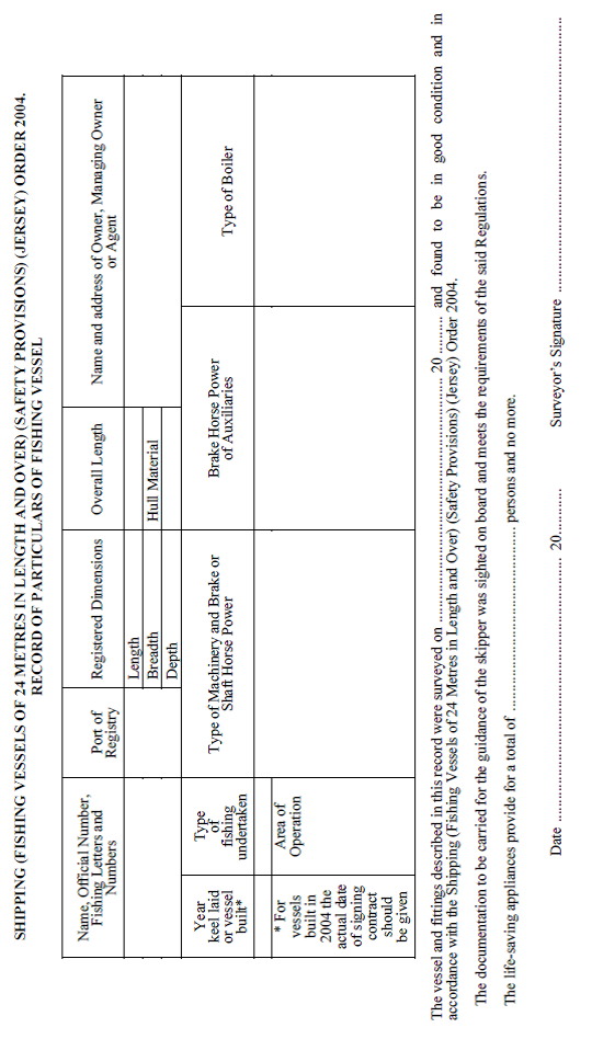
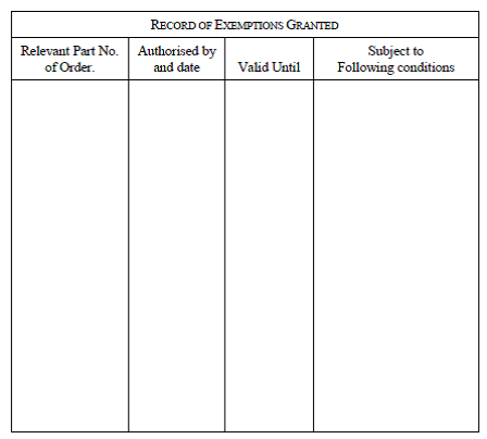
SCHEDULE 3
(Articles 18 and 75)
Information as to stability of fishing vessels
The book to be kept on board the vessel pursuant to Article 75
shall contain the following information:
1. A
statement of the vessel’s name, port of registry, official number,
registration letters, principal dimensions, gross and register tonnages,
displacement and minimum freeboard in the deepest foreseeable operating
condition shall be included in such information.
2. A
profile plan of the vessel drawn to scale showing with their names all
compartments, tanks, storerooms, crew accommodation spaces and the position of
the midpoint of the length between perpendiculars shall be provided.
3. A
tabular statement of the capacity and position of the centre of gravity,
longitudinally and vertically of every compartment available for the carriage
of cargo fuel, stores, feed water, domestic water, water ballast, and crew and
effects shall be included in such information. The free surface function
defined in paragraph 9 shall also be included for each tank designed to
carry liquid. Details of the volumetric-centre of the total internal volume of
the fish-hold shall be included in such information. The calculation may take
into account the effect of assuming a void space between the top of the catch
and the underside of the deckhead provided that under normal operating
conditions provision has been made for the effective control of the loading in order
to ensure that the actual void space will always be equal to or greater than
that assumed in such a calculation.
4. Where
deck cargo is carried by a vessel the estimated weight and disposition of deck
cargo the vessel may be expected to carry while satisfying the stability
criteria set out in Article 18 shall be included in such information.
5. A
diagram or tabular statement shall be provided showing for a suitable range of
mean draughts and at the trim stated, the following hydrostatic particulars of
the vessel –
(i) the
heights of the transverse metacentres;
(ii) moments
to change trim one centimetre;
(iii) tonnes
per centimetre immersion;
(iv) longitudinal
position of the centre of flotation;
(v) vertical
and longitudinal positions of the centre of buoyancy;
(vi) displacement
in tonnes.
Where vessels have raked keels the same datum shall be used for the
hydrostatics as was employed in determining the requirements of paragraph 3
above. In such cases full information shall be included in respect of the rake
and dimensions of the keel and may be given in the form of a diagram.
6. A
diagram shall be provided showing cross curves of stability indicating the
assumed position of the axis from which the righting levers are measured and
the trim which has been assumed. Where vessels have raked keels any datum other
than a line through the top of the keel amidships shall be clearly defined.
7. The
information provided under paragraphs 5 and 6 shall be at such a nominal trim
that represents accurately the vessel in all normal operating trims. Where
calculations show that there are significant numerical variations in these
operating trims the information provided under paragraphs 5 and 6 shall be
repeated over such a range of trims to allow an accurate interpolation of such
information at any normal operating trim.
8. Superstructure
deckhouses, companionways located on the freeboard deck, including hatchway
structures may be taken into account in deriving such cross-curves of stability
provided that their location, integrity and means of closure will effectively
contribute to the buoyancy.
9. An
example shall be included in such information to show the corrections applied
to the transverse metacentric height and righting levers (GZ) for the effects
of the free surfaces of liquids in tanks and shall be calculated and taken into
account as follows –
(i) the metacentric height in metres shall be reduced by
an amount equal to the total of the free surface functions for each tank
divided by the vessel’s displacement in tonnes. For each tank the free
surface function is given by –
1.025 x pi
where –
|
p = specific gravity of the
liquid;
|
|
I = transverse moment of inertia
of the surface;
|
|
(i.e.
|

|
where L = length and B = breadth
of the surface of metres);
|
|
i.e. correction =
|

|
|
|
|
|
(ii) the
righting lever (GZ) curves shall be corrected by either –
(a) adding the free surface
correction calculated under (i) to the value in metres of the calculated height
of centre of gravity of the vessel above the datum; or
(b) making direct
calculations of the heeling moment due to the liquid surface being inclined at
the selected angle of heel where such calculations take proper account of the
position of liquid surface in relation to the geometric configuration of the
tank. The correction to the righting lever (GZ) at any selected angle of heel
shall then be the summation of the individual heeling moments of the tanks
considered, divided by the vessel’s displacement.
10. A
stability statement and diagram shall be provided for the usual condition of
the vessel –
(a) in
the lightship condition:
the vessel shall be assumed to be empty except for water in boilers
and liquid in pipe systems including header tanks. The weight and position of
the centre of gravity of any permanent ballast or fishing gear shall be
indicated where this is known;
(b) in
each of the following circumstances so far as they may be applicable to the
vessel in its foreseeable operating conditions –
(i) on departure from
port:
the vessel shall be assumed to be loaded with the necessary
equipment, materials and supplies including ice, fuel, stores and water;
(ii) on
arrival at fishing grounds:
as sub-paragraph (i) but account taken of the consumption of
fuel and stores:
(iii) on
arrival at fishing grounds:
as sub-paragraph (ii) but the appropriate icing-up allowance as
set out in paragraph 14 shall be taken into account;
(iv) on
departure from fishing grounds:
the vessel shall be assumed to be loaded with its maximum catch but
account taken of the consumption of fuel and stores;
(v) on departure from
fishing grounds:
as sub-paragraph (iv) but the appropriate icing-up allowance as
set out in paragraph 14 shall be taken into account;
(vi) on
departure from fishing grounds:
the vessel shall be assumed to be loaded with 20% of its maximum
catch but account taken of the consumption of fuel and stores;
(vii) on
departure from fishing grounds:
as sub-paragraph (vi) but the appropriate icing-up allowance as
set out in paragraph 14 shall be taken into account;
(viii) on arrival at
port with maximum catch:
account shall be taken of the consumption of fuel and stores;
(ix) on
arrival at port with 20% maximum catch:
account shall be taken of the consumption of fuel and stores;
(x) if any part of the
catch normally remains on deck, further statements and diagrams appertaining to
that condition in all the appropriate circumstances set out in sub-paragraphs (iv)
to (ix) inclusive shall be provided.
The total free surface correction for the effect of liquid in tanks
shall be applied to each loading condition set out in the foregoing provisions
of this paragraph. The free surface correction shall take into account the amounts
of fuel, lubricating oil, feed and fresh water in the vessel in each such
loading condition.
The working instructions placed on board pursuant to Article 76
shall generally be based upon the conditions specified in this paragraph and
shall form part of this stability statement.
11. Where
provision is made in a particular area of the vessel for the washing and
cleaning of the catch which could lead to an accumulation of loose water a
further statement and diagram shall be provided appropriate to that condition
which takes into account the adverse effects of such loose water, it being
assumed that –
(i) the
amount of loose water on deck is determined by the size and disposition of the
retaining devices; and
(ii) in
all other respects the vessel is loaded in accordance with paragraph 10(iv)
or paragraph 10(vi), whichever is the less favourable with regard to the
vessel’s stability.
12. Each
stability statement shall consist of –
(i) a
profile drawn to a suitable scale showing the disposition of the deadweight
components;
(ii) a
tabular statement of all the components of the displacement including weights,
positions of centres of gravity, transverse metacentric height corrected for
free surface effects, trim and draughts;
(iii) a
diagram showing a curve of righting levers (GZ), corrected for free surfaces
effects and derived from the cross-curves of stability, showing, if
appropriate, the angle at which the lower edges of any opening which cannot be
closed watertight will be immersed. The diagram shall also show the
corresponding numerical values of the stability parameters defined in Article 18.
13. The
information provided under paragraph 12(iii) may be supplemented by a
graph or tabular statement showing the maximum permissible deadweight moment
over a range of draughts which shall cover foreseeable operating conditions. At
any given draught this maximum permissible deadweight moment value is the total
vertical moment, about a convenient base line, of all the component weights of
the total deadweight which, at that draught, will ensure minimum compliance
with the stability criteria requirements of Article 18. If an allowance
for the weight due to icing-up is required this shall be taken into account by
a suitable reduction in the permissible moment. Where the stability information
is supplied in accordance with the requirements of this paragraph the tabular
statement required in accordance with paragraph 12(ii) shall include the
deadweight moment appropriate to each condition and an example shall be added
to the stability information to demonstrate the assessment of the stability.
14. The
icing-up allowances which represent the added weight due to ice accretion on
the exposed surfaces of the hull, superstructure, deck, deckhouses and companionways
shall be calculated as follows –
(i) full icing
allowance:
all exposed horizontal surfaces (decks, house tops, etc.) shall be
assumed to carry an ice weight of 30 kilogrammes per square metre. The
projected lateral area of the vessel above the waterline (a silhouette) shall
be assumed to carry an ice weight of 15 kilogrammes per square metre.
The height of the centre of gravity shall be calculated according to
the heights of the respective areas and in the case of the projected lateral
area the effect of sundry booms, rails, wires, etc., which will not have been
included in the area calculated shall be taken into account by increasing by 5%
the weight due to the lateral area and the moment of this weight by 10%. This
allowance shall apply in winter (1st November to 30th April inclusive in
the northern hemisphere) to vessels which operate in the following
areas –
(a) the
area north of latitude 66°30N. between longitude 10°W and the Norwegian
Coast;
(b) the
area north of latitude 63°N between longitude 28°W and 10°W;
(c) the
area north of latitude 45°N. between the North American continent and longitude
28°W;
(d) all
sea areas north of the European, Asian and North American continents east and
west of the areas defined in (a), (b) and (c);
(e) Bering
and Okhotsk seas and Tatar Strait;
(f) South
of latitude 60°S.
(ii) half
of the full icing allowance:
this shall be taken as one half of that calculated under sub-paragraph (i)
and shall apply in winter to vessels which operate in all areas north of
latitude 61°N between longitude 28°W and the Norwegian coast and south
of the areas defined as the lower limit for full icing allowance between
longitude 28°W and the Norwegian coast.
15. Information
shall be provided in respect of the assumptions made in calculating the
condition of the vessel in each of the circumstances set out in paragraph 10
for the following –
(i) duration
of the voyage in terms of days spent in reaching the fishing grounds, on the
grounds and returning to port;
(ii) the
weight and disposition of the ice in the hold at departure from port including
the heights of stowage;
(iii) consumption
rates during the voyage for fuel, water, stores and other consumables;
(iv) ratio by
weight of the ice packed with the catch in the fish hold;
(v) melting
rates for each part of the voyage of the ice packed with the catch and the ice
remaining unused in the hold.
16. A
copy of a report of an inclining test of the vessel and the derivation
therefrom of the lightship particulars shall be provided.
17. A
statement shall be given by or on behalf of the owner of the vessel that the
statements and diagrams supplied with respect to the operating conditions set
out in paragraph 10 are based on the worst foreseeable service conditions
in respect of the weights and disposition of fish carried in the hold or on
deck, ice in the hold, fuel, water and other consumables.
SCHEDULE 4
(Article 84(1))
General requirements for lifeboats
1. Every
lifeboat shall be constructed with rigid sides.
2. In
any lifeboat fitted with a rigid shelter the shelter shall be capable of being
readily opened from both inside and outside and shall not impede rapid
embarkation and disembarkation or the launching and handling of the lifeboat.
Such a shelter where fitted may be accepted as complying with the requirements
of Article 92(1)(x).
3. Every
lifeboat except wooden lifeboats made of planks shall have a block co-efficient
of the cubic capacity as determined in accordance with Schedule 5 of not
less than 0.64.
4. Every
lifeboat shall be of such form and proportions that it shall have ample
stability in a seaway and sufficient freeboard when loaded with its full
complement of persons and equipment.
5. Every
lifeboat shall be so constructed that it shall be capable of maintaining
positive stability when open to the sea and loaded with its full complement of
persons and equipment.
6. Every
lifeboat shall be properly constructed for the purpose for which it is intended
and shall be of sufficient strength to permit its being safely lowered into the
water when loaded with its full complement of persons and equipment. It shall
be of such strength that it will not suffer residual deflection if subjected to
an overload of at least 25%.
7. No
lifeboat shall be less than 4.9 metres in length except that where this Order
permits a lifeboat to be carried as an alternative to a Class C boat, the
length of such lifeboat shall not be less than that of the Class C boat as
determined in accordance with paragraph 1 of Schedule 8.
8. No
lifeboat when laden with its full complement of persons (calculated at
75 kilogrammes per person) and equipment shall weigh more than
20 tonnes.
9. In
every lifeboat all thwart and side seats shall be fitted as low in the lifeboat
as practicable and bottom boards shall be fitted.
10. Every
lifeboat shall have a mean sheer at least equal to 4% of its length. The sheer
shall be approximately parabolic in form.
11. Every
lifeboat shall be fitted with internal buoyancy appliances which shall consist
either of air cases or buoyant material which shall not be adversely affected
by oil or oil products and which shall not adversely affect the boat.
12. In
every lifeboat the total volume of the internal buoyancy appliances shall be
such that it will be at least equal to the sum of the volumes of:
(a) that
required to float the lifeboat and its full equipment when the lifeboat is
flooded and open to the sea so that the top of the gunwale amidships is not
submerged; and
(b) that
equal to 10% of the cubic capacity of the lifeboat.
SCHEDULE 5
(Article 84(2))
Calculation of cubic capacity of lifeboats
1. Subject
to the provisions of paragraph 4, the cubic capacity of a lifeboat for the
purposes of this Order shall be measured in cubic metres and shall be
determined by Stirling’s (Simpson’s) Rule, which may be considered
as given by the following formula –
Cubic Capacity = (4A + 2B + 4C), where L denotes the length of the
lifeboat in metres from the inside of the shell at the top of the stem to the
corresponding point at the top of the stern post; in the case of a lifeboat
with a square stern the length is measured to the inside of the top of the
transom; and
A, B, C, denote respectively the areas of the cross-sections at the
quarter length forward, amidships and the quarter length aft which correspond
to the 3 points obtained by dividing L into 4 equal parts (the areas
corresponding to the 2 ends of the lifeboat shall be considered
negligible).
The areas A, B, C shall be deemed to be given in square metres by
the successive application of the following formula to each of the
3 cross-sections –
Area = (a + 4b + 2c + 4d + e), where h denotes the depth measured in
metres inside the shell from the keel to the level of the gunwale, or, in
certain cases, to a lower level as determined hereafter; and a, b, c, d, e
denote the horizontal breadths of the lifeboat measured in metres inside the
shell at the upper and lower points of the depth and at the 3 points obtained
by dividing h into 4 equal parts (a and e being the breadths at the extreme
points, and c at the middle point of h).
The capacity of a square-sterned lifeboat shall be calculated as if
the lifeboat had a pointed stern.
2. If
the sheer of the gunwale, measured at 2 points situated at a quarter of
the length of the lifeboat from the ends, exceeds 1% of the length of the
lifeboat, the depth employed in calculating the area of the
cross-section A or C shall be deemed to be the depth amidships plus 1% of
the length of the lifeboat.
3. If
the depth of the lifeboat amidships exceeds 45% of the breadth, the depth
employed in calculating the area of the amidship cross-section B shall be
deemed to be equal to 45% of the breadth, and the depth employed in calculating
the areas of the quarter length sections A and C is obtained by increasing this
last figure by an amount equal to 1% of the length of the lifeboat:
Provided that in no case shall the depths employed in the
calculations exceed the actual depths at these points.
4. Unless
the owner of the lifeboat requires the cubic capacity to be determined by exact
measurements, the cubic capacity of a lifeboat constructed of wooden planks may
be assumed to be the product of the length, the breadth and the depth
multiplied by 0.6 if this formula does not give a greater capacity than that obtained
by the formula set out in paragraph 1. The dimensions shall be measured in
the following manner –
Length – from the intersection of the outside of the
planking with the top of the stem to the corresponding point at the stern post,
or in the case of a square-sterned lifeboat, to the after side of the top of
the transom;
Breadth – from the outside of the planking at the point
where the breadth of the lifeboat is greatest;
Depth – amidships inside the planking from the keel to
the level of the top of the gunwale, but the depth used in calculating the
cubic capacity may not in any case exceed 45% of the breadth.
5. The
cubic capacity of a motor lifeboat or a lifeboat fitted with other propelling
gear shall be obtained from the gross capacity by deducting a volume equal to
that occupied by the motor and its accessories or the gearbox of the other
propelling gear.
SCHEDULE 6
(Article 84(5)(a))
Requirements for machinery of motor lifeboats
1. The
engine shall be capable of being readily started in cold weather and of running
reliably under conditions of extremes of temperatures.
2. The
engine shall operate properly under conditions of at least 10 degrees list
and 10 degrees trim. Circulating water pumps where fitted shall be
self-priming.
3. The
engine and its accessories, including the fuel tank, pipes and fittings, shall
be adequately protected to ensure reliable operation under conditions likely to
arise at sea during adverse weather. The engine casing shall additionally be
fire-resisting and in the case of air-cooled diesel engines shall be so
designed that the supply of cooling air is not restricted.
4. Means
shall be provided in all lifeboats to prevent the spread of oil. In a wooden
lifeboat a metal tray shall be fitted under the engine.
5. The
fuel tank shall be substantially constructed, securely fixed in position with a
metal tray underneath and fitted with suitable filling, vapour venting and
relief arrangements. No part of the tank or its connections nor any part of the
fuel piping or fittings shall depend on soft solder for tightness, and tanks
made of steel shall be protected externally against corrosion by sea water by
metal spraying or similar means. The tanks and its connections shall be capable
of withstanding hydraulic pressure corresponding to a head of at least
4.5 metres. A cock shall be fitted at each end of the fuel pipe.
6. The
engine and fuel tank spaces shall be efficiently ventilated.
7. The
shafting and other moving parts shall be fenced where necessary to protect the
persons in the lifeboat from injury.
SCHEDULE 7
(Article 85)
Requirements for Class C boats
1. Every
Class C boat shall be an open boat constructed with rigid sides.
2. The
boat shall be of such form and proportions that it shall have ample stability
in a seaway and sufficient freeboard when loaded with its equipment and the
number of persons specified in column (3) of paragraph 3.
3. The
length of the boat and the number of persons for whom seating shall be provided
in the boat shall be determined in accordance with the following
table –
|
(1)
|
(2)
|
(3)
|
|
Number of persons
on board the
vessel
|
Minimum length
of boat in
metres
|
Minimum seating
capacity of
boat (persons)
|
|
More than 8
8
6 or 7
5
4 or less
|
4.8
4.5
4.2
3.9
3.6
|
9
8
7
5
4
|
4. All
thwart and side seats in the boat shall be fitted as low in the boat as
practicable and bottom boards shall be fitted.
5. The
boat shall be square-sterned and shall have a mean sheer at least equal to 5%
of its length.
6. The
boat shall be fitted with internal buoyancy appliances which shall be so placed
as to secure stability when the boat is fully laden under adverse weather
conditions.
7. Every
boat shall be fitted with internal buoyancy appliances which shall consist
either of air cases or buoyant material which shall not be adversely affected
by oil or oil products and which shall not adversely affect the boat.
8. The
total volume of the internal buoyancy appliances shall be such that it will be
at least equal to the sum of the volumes of –
(a) that
required to float the boat and its full equipment when the boat is flooded and
open to the sea so that the top of the gunwale amidships is not submerged; and
(b) that
equal to 7.5% of the cubic capacity of the boat which shall be determined in
the same manner as that prescribed for lifeboats in Schedule 5.
SCHEDULE 8
(Article 93)
Requirements for inflatable boats
Every inflatable boat shall comply with the following
requirements –
1. The
overall length of the boat shall be not less than 3 metres and the boat
shall be of such form and proportions as to have ample stability in a seaway
when afloat in the empty, laden or swamped condition. The boat shall be
suitable for the accommodation of at least 6 persons.
2. The
boat shall be of sufficiently robust construction to survive when fully loaded,
without such deterioration as would involve any loss of seaworthiness, for
30 days afloat under extremes of temperatures (60°C to minus 30°C)
and in weather likely to be encountered at sea anywhere in the world.
3. All
materials and components used in the construction of the boat and its
accessories shall be able to withstand the worldwide seagoing climatic
conditions referred to in paragraph 2. The boat and its accessories shall
be resistant to the effects of humidity when stowed on board a vessel and all
fabrics, cordage, webbing and thread shall be rot-proof. The boat shall be so
constructed that it is not adversely affected by oil or oil products.
4. The
boat shall possess a sufficient margin of durability to ensure that its
performance will not be affected after 24 months’ stowage on board a
vessel in a weather deck stowage with a minimum of additional protection.
5. The
main buoyancy chambers forming the boundary of the boat shall on inflation
provide at least 0.17 cubic metres of volume for each person the boat
is certified to accommodate. The diameter of the main buoyancy chambers of
single tube boats shall be at least 0.43 metres.
6. The
main buoyancy chambers shall be divided into at least 2 compartments along
each side and one compartment in the bow, making a minimum total of
5 compartments.
7. In
boats of more than one tube the volume of either tube shall not exceed 60% of
the total volume.
8. At
least one thwart shall be fitted so that the boat can be rowed satisfactorily.
9. The
floor of the boat shall be waterproof and shall provide an efficient working
platform.
10. A
transom which shall not be inset by more than 20% of the overall length of the
boat shall be provided.
11. A
bow cover of a highly visible colour and extending for at least 15% of the overall
length of the boat shall be provided.
12. A
non-return valve shall be fitted to each buoyancy chamber for manual inflation.
13. A
safety relief valve designed to operate at a pressure not exceeding 125% of the
designed working pressure of the buoyancy chamber shall be fitted in each
buoyancy chamber. Means for deflating shall be fitted in each chamber.
14. The
boat shall be provided with the following equipment –
(a) a
painter of adequate length and size;
(b) a
grab line secured round the outside of the boat and a grab line fitted round
the inside of the boat;
(c) a
drain plug;
(d) a
crutch or steering grommet in the transom;
(e) hand-holds
or straps for the purpose of righting the boat from the inverted position;
(f) a
sea anchor attached to the boat by a line of adequate strength at least
9 metres in length;
(g) an
efficient manually operated bellows or pump;
(h) 2 buoyant
rescue quoits each attached to 18 metres of light buoyant line;
(i) at
least 2 buoyant oars and 2 buoyant paddles;
(j) a
safety knife;
(k) bridle
slinging arrangements to enable the boat to be lowered into or raised from the
water;
(l) a
bailer and 2 sponges;
(m) a repair
kit in a suitable container for repairing punctures in buoyancy compartments;
(n) one
waterproof electric torch suitable for morse signalling together with one spare
set of batteries and one spare bulb in a waterproof container.
SCHEDULE 9
(Article 87)
REQUIREMENTS FOR LIFERAFTS
PART 1 – Inflatable liferafts
EVERY inflatable liferaft shall comply with the following requirements –
(a) the
liferaft shall be so constructed that, when fully inflated and floating with
the cover uppermost, it shall be stable in a seaway;
(b) the
liferaft shall be so constructed that if it is dropped into the water from a
height of 18 metres, neither the liferaft nor its equipment will be
damaged;
(c) the
construction of the liferaft shall include a cover of a highly visible colour
which shall automatically be set in place when the liferaft is inflated. This
cover shall be capable of protecting the occupants against injury from
exposure, and means shall be provided for collecting rain. The top of the cover
shall be fitted with a lamp which derives its luminosity from a sea-activated
cell and a similar lamp shall also be fitted inside the liferaft;
(d) the
liferaft shall be fitted with a painter and shall have a lifeline ucketed round
the outside. A lifeline shall also be fitted round the inside of the liferaft;
(e) the
liferaft shall be capable of being readily righted by one person if it inflates
in an inverted position;
(f) the
liferaft shall be fitted at each opening with efficient means to enable persons
in the water to climb on board;
(g) the
liferaft shall be contained in a valise or other container so constructed as to
be capable of withstanding hard wear under conditions encountered at sea. The
liferaft in its valise or other container shall be inherently buoyant;
(h) the
buoyancy of the liferaft shall be so arranged as to ensure by a division into
an even number of separate compartments, half of which shall be capable of
supporting out of the water the number of persons which the liferaft is fit to
accommodate, or by some other equally efficient means, that there is a
reasonable margin of buoyancy if the raft is damaged or partially fails to
inflate;
(i) the
total weight of the liferaft, its valise or other container and its equipment
shall not exceed 180 kilogrammes;
(j) the
number of persons which a liferaft shall be deemed fit to accommodate shall be
equal to –
(i) the greatest
whole number obtained by dividing by .096 the volume measured in cubic metres
of the main buoyancy tubes (which for this purpose shall include neither the
arches nor the thwart or thwarts if fitted) when inflated; or
(ii) the
greatest whole number obtained by dividing by 3,720 the area measured in square
centimetres of the floor (which for this purpose may include the thwart or
thwarts if fitted) of the liferaft when inflated;
whichever number shall be the less;
(k) the
floor of the liferaft shall be waterproof and shall be capable of being
sufficiently insulated against cold, either –
(i) by means of one
or more compartments which the occupants can inflate if they so desire, or
which inflate automatically and can be deflated and re-inflated by the occupants;
or
(ii) by
other equally efficient means not dependent on inflation;
(l) the
liferaft shall be inflated by a gas which is not injurious to the occupants and
the inflation shall take place automatically either on the pulling of a line or
by some other equally simple and efficient method. Means shall be provided
whereby a topping-up pump or bellows may be used to maintain pressure;
(m) the
liferaft shall be of suitable material and construction, and shall be so
constructed as to be capable of withstanding exposure for 30 days afloat in all
sea conditions;
(n) every
liferaft which is designed for use with a launching appliance shall be properly
constructed for the purpose for which it is intended and shall be of sufficient
strength to permit it to be safely lowered into the water when loaded with its
full complement of persons and equipment;
(o) the
liferaft shall have a carrying capacity calculated in accordance with sub-paragraph (j)
of not less than 6 persons or more than 25 persons; provided that in
vessels in which the total number of persons on board is less than 6, the
minimum carrying capacity of the liferaft shall be 4 persons;
(p) the
liferaft shall be capable of operating throughout a temperature range of
66°C to minus 30°C;
(q) the
liferaft shall be fitted with arrangements enabling it to be readily towed;
I every
liferaft carried on a vessel which is provided with portable radio equipment
which complies with the specification set forth in Part 1 of Schedule 14
shall be provided with arrangements for accommodating properly in the operating
position the aerial referred to in the specification set out in the said Schedule;
(s) notwithstanding
the provisions of the foregoing paragraphs of this Part of this Schedule, any
liferaft the inflatable chambers or floor of which are made of rubber-proofed
cotton shall be treated as not complying with the requirements of this Part of
this Schedule.
PART 2 – Rigid liferafts
(Article 87)
Every rigid liferaft shall
comply with the following requirements –
(a) the
liferaft shall be so constructed that if it is dropped into the water from its
stowed position neither the liferaft nor its equipment will be damaged;
(b) any
liferaft which is designed for use with a launching appliance shall be properly
constructed for the purpose for which it is intended and shall be of sufficient
strength to permit it to be safely lowered into the water when loaded with its
full complement of persons and equipment;
(c) the
liferaft shall be so constructed that its air cases or buoyant material are
placed as near as possible to its sides;
(d) the
deck area of the liferaft shall be situated within that part of the liferaft
which affords protection to its occupants. The nature of the deck shall be such
as to prevent so far as practicable the ingress of water and it shall
effectively support the occupants out of the water;
(e) the
liferaft shall be fitted with a cover or equivalent arrangement of a highly
visible colour, which shall be capable of protecting the occupants against
injury whichever way up the liferaft is floating;
(f) the
equipment of the liferaft shall be so stowed as to be readily available
whichever way up the liferaft is floating;
(g) the
total weight of any liferaft and its equipment shall not exceed
180 kilogrammes except that such total weight may be exceeded where the
liferaft is capable of being launched from both sides of the vessel or if means
are provided for putting it into the water mechanically on either side of the
vessel;
(h) the
liferaft shall at all times be effective and stable when floating either way
up;
(i) the
number of persons which the liferaft shall be deemed fit to accommodate shall
be equal to –
(i) the greatest
whole number obtained by dividing by .096 the volume measured in cubic metres
of the air cases or buoyant material; or
(ii) the
greatest whole number obtained by dividing by 3,720 the deck area of the
liferaft measured in square centimetres; whichever number shall be the less;
(j) the
liferaft shall have a painter attached and a lifeline securely ucketed round
the outside. A lifeline shall also be fitted round the inside of the liferaft;
(k) the
liferaft shall be fitted at each opening with efficient means to enable persons
in the water to climb on board;
(l) the
liferaft shall be so constructed as not to be affected by oil or oil products;
(m) a buoyant
light of the electric battery type shall be attached to the liferaft by a
lanyard;
(n) the
liferaft shall be fitted with arrangements enabling it to be readily towed;
(o) liferafts
shall be so stowed as to float free in the event of the vessel sinking;
(p) every
liferaft carried on a vessel which is provided with portable radio equipment
which complies with the specification set forth in Part 1 of Schedule 14
shall be provided with arrangements for accommodating properly in the operating
position the aerial referred to in the specification set out in the said Schedule.
SCHEDULE 10[135]
(Article 89)
REQUIREMENTS FOR LIFEBUOYS
1. Every
lifebuoy shall be constructed of cork, evenly formed and securely plugged, or
of other equally efficient buoyant material which shall not be adversely
affected by oil or oil products, and shall be capable of floating in fresh
water for at least 24 hours with 14.5 kilogrammes of iron suspended
from it.
2. Every
lifebuoy made of plastic or other synthetic compounds shall be capable of
retaining its buoyant properties and durability in contact with sea water or
oil products, or under variation of temperature or climatic changes prevailing
in open sea voyages.
3. A
lifebuoy shall not be filled with rushes, cork shavings, granulated cork or any
other loose granulated material, and its buoyancy shall not depend upon air
compartments which require to be inflated.
4. The
inside diameter of a lifebuoy shall be 455 millimetres and the outside
diameter 760 millimetres. The major axis of the section shall be
150 millimetres. The minor axis of the section shall be
10 millimetres.
5. Every
lifebuoy shall be of a highly visible colour.
6. Every
lifebuoy shall be marked in block letters with both the name and the port of
registry or the fishing number of the vessel in which it is carried. Lifebuoys
constructed of materials other than cork shall be permanently marked with the
manufacturer’s trade name for that product.
7. Every
lifebuoy shall be fitted with grab lines which shall be of good quality
unkinkable line and well secured at 4 equidistant points providing
4 loops of line each not less than 700 millimetres long.
8. The
weight of a lifebuoy shall not exceed 6.15 kilogrammes when newly constructed.
SCHEDULE 11[136]
(Articles 78(3)(d)(i), 79(5)(d)(i) and 80(3)(d)(i))
Requirements for lifebuoy marker smoke signals
1. Every
smoke signal shall be fitted with a self-contained means of ignition, and with
means for being efficiently attached to a lifebuoy.
2. The
signal shall be capable of emitting dense orange-coloured smoke for at least 15
minutes while floating in water.
3. The
signals shall be water proofed and capable of functioning after immersion for 2
hours in water under a head of one metre.
4. After
completion of the ignition cycle the signal shall continue to function after
immersion for 10 seconds under a head of water of 10 centimetres.
5. The
signal shall be capable of quick release from the stowed position.
6. The
signal shall be capable of functioning after being dropped into water from a
height of 25 metres at a speed of 30 knots.
7. The
signal shall be safe to operate in oil covered waters.
8. Lifebuoy
marker smoke signals may also be provided with self igniting lights which are
required under Article 31.
9. All
components, composition and ingredients of the signals shall be of such
character and quality as to enable them to maintain their serviceability under
good average storage conditions in the marine environment for a period of at
least 3 years.
10. The
date of manufacture and the date of expiry shall be marked indelibly on the
signal.
11. Clear
and concise directions for use in the English language supported by
illustrations shall be printed indelibly on the signal.
SCHEDULE 12[137]
(Articles 78(3)(b), 79(5)(b) and 80(3)(b))
REQUIREMENTS FOR LIFEJACKETS
PART 1
1. Subject
to the provisions of paragraph 7 of this Part of this Schedule, every
lifejacket for use by a person weighing 32 kilogrammes or more shall
provide a minimum of 15.8 kilogrammes buoyancy in fresh water for
24 hours.
2. Every
such lifejacket shall be marked indelibly on both sides in letters not less
than 12 millimetres in size with the words “PERSON OF
32 KILOGRAMMES OR MORE” and on one side only with the maker’s
name or other identification mark.
3. Every
such lifejacket shall also comply with the following requirements –
(a) it
shall be so constructed as to eliminate as far as possible all risk of its
being put on incorrectly and it shall be capable of being worn inside out;
(b) it
shall turn the wearer on entering still water to a safe floating position
within 5 seconds with the body inclined backwards from its vertical
floating position and shall support the head of the conscious or unconscious
wearer so that the mouth shall not be less than 150 millimetres above the
water;
(c) it
shall not be adversely affected by oil or oil products;
(d) it
shall be of a highly visible colour;
(e) it
shall be fitted with a ring or loop or similar device of adequate strength to
facilitate rescue;
(f) it
shall be made of materials of low flammability and the fabric with which it is
covered and its tapes shall be rotproof;
(g) it
shall be fitted with an approved whistle firmly attached by a lanyard;
(h) it
shall have fastening tapes securely attached to the lifejacket cover which
comply with British Standards Specification
No. B.S. 2F 49: 1959 and are capable of taking a load of
140 kilogrammes. The method of fastening the tapes shall be such as to be
easily understood and capable of being readily carried out. Metal fastenings
when used shall be of a size and strength consistent with the fastening tapes
and of corrosion resistant material; and
(i) it
shall allow the wearer to jump a vertical distance of 6 metres into the
water without injury and without dislodgement of the lifejacket.
4. The
buoyancy of every such lifejacket shall be provided by kapok or other equally
effective buoyant material.
5. Every
such kapok lifejacket shall, in addition to complying with the requirements of paragraph
1 to 4 of this Part of this Schedule, comply with the following
requirements –
(a) it
shall contain not less than one kilogramme of kapok;
(b) the
kapok shall be of good flotation quality, well teased, evenly packed and free
from seeds and other foreign matter;
(c) the
kapok shall be protected from the effects of oil or oil products so that the
loss of buoyancy in the lifejacket, after floating in disturbed water
containing a layer of not less than 3 millimetres in depth of a mixture of
gas oil for a period of 48 hours, shall not exceed 2% of the initial
buoyancy and for the purpose of this test the lifejacket shall be loaded with
weights equal to half its initial buoyancy;
(d) the
covering shall be of pre-shrunk cotton material or a suitable synthetic
material the weight of which in loom state per linear yard shall be not less
than 170 grammes for a width of 685 millimetres and in proportion for
other widths. The fabric shall be free from admixture of sizing or other
foreign matter. The threads per inch in loomstate shall be warp 44 two-fold
threads and weft 34 two-fold threads; and
(e) the
sewing shall be carried out with thread of undyed linen yarn having a count of
25 lea, 3 cord reverse twist (resultant Tex count 66), satin
finish and complying with the specifications in Clauses 2, 3 and 4 (except paragraph 4(a))
of British Standards Specification No. BS. 4F 34: 1960: for
thread of that count.
6. Every
such lifejacket using a buoyant material other than kapok shall, in addition to
complying with the requirements of paragraphs 1 to 4 and paragraph 5(d)
of this Part of this Schedule, comply with the following
requirements –
(a) the
material shall not stable.
7. Every
lifejacket the buoyancy of which depends on inflation, which may be carried for
use by members of the crew shall comply with the requirements of paragraph 3
of this Part of this Schedule and in addition shall comply with the following
requirements –
(a) it
shall have 2 separate buoyancy compartments in either of the following
forms –
(i) one compartment
of inherent buoyancy equal to at least 9 kilogrammes and one air
compartment of at least 6 kilogrammes; or
(ii) 2 separate
air compartments each of at least 9 kilogrammes buoyancy;
(b) it
shall be marked indelibly on both sides in letters not less than
25 millimetres in size with the words “CREW ONLY” and on one
side only with the maker’s name or other identification mark in smaller
letters; and
(c) it
shall be capable of being inflated both mechanically and by mouth.
PART 2
1. Every
lifejacket for use by a person weighing less than 32 kilogrammes shall
provide a minimum buoyancy of 6.8 kilogrammes in fresh water for
24 hours.
2. Every
such lifejacket shall be marked indelibly on both sides in letters not less
than 12 millimetres in size with the words “FOR PERSON UNDER
32 KILOGRAMMES” and on one side only with the maker’s name or
other identification mark.
3. Every
such lifejacket shall comply with the requirements of paragraphs 3 and 4
of Part 1 of this Schedule.
4. Every
such kapok lifejacket shall contain not less than 425 grammes of kapok and
shall in addition to complying with the requirements of paragraph 1 to 3
of this Part of this Schedule comply with the requirements of paragraph 5(b),
(c) and (d) of Part 1 of this Schedule.
5. Every
such lifejacket using a buoyant material other than kapok shall, in addition to
complying with the requirements of paragraphs 1 to 3 of this Part of this Schedule
comply with paragraph 5(d), and 6(a) and (b) of Part 1 of this Schedule.
SCHEDULE 13
(Article 91)
Requirements for line-throwing appliances
1. Every
line-throwing appliance shall consist of a rocket pistol and 4 individual
rockets with 4 lines, or 4 separate self-contained units each of
which contains a rocket and line ready for use.
2. The
appliance shall be so constructed that the end from which the rocket is ejected
can be positively identified by day or night.
3. The
lines used in line-throwing appliances shall have a breaking load of not less
than 2,000 newtons.
4. Every
line-throwing appliance shall be capable of throwing a line a minimum of
12.0 millimetres in circumference a distance of 230 metres in calm
weather.
5. Every
line-throwing appliance shall be capable of throwing the line in such a manner
that the lateral deflection on either side of the direction of firing does not
exceed 10% of the length of flight of the rocket in calm weather.
6. The
rocket (in the case of a pistol fired rocket) or the assembly (in the case of
an integral rocket and line) shall function after immersion for one minute
under a head of water of 10 centimetres.
7. The
lines and the rockets together with the means of igniting them, shall be kept
in suitable cases to afford protection from the weather.
8. All
components, compositions and ingredients of the rockets and the means of
igniting them shall be of such character and quality as to enable them to
maintain their serviceability under good average storage conditions in the
marine environment for a period of at least 3 years.
9. The
date of manufacture and the date of expiry shall be marked indelibly on the
rockets and these date markings shall be similarly stamped on the cartridges.
10. Clear
and concise directions for use in the English language, supported by
illustrations, shall form an integral part of the appliance.
SCHEDULE 14[138]
(Articles 78(3)(b), 79(5)(a) and 80(3)(a))
Requirements for portable radio equipment for use in lifeboats and
liferafts
Every portable radio equipment for survival craft shall comply with
one of the following performance specifications –
Part I. Man powered
equipment
(a) a Man-Powered
Portable Radio Equipment for Survival Craft, 1964, issued by the Postmaster
General, as reprinted in 1967;
(b) a Man-Powered Portable
Radio Equipment for Survival Craft, MPT 1207 issued by the Secretary of State
for the Home Department.
Part II. Battery Powered
equipment
(c) a Compulsory
Radiotelephone Distress Equipment suitable for use in Fishing Boats’
Survival Craft, 1965, issued by the Postmaster General, as reprinted in 1968.
(d) a Radiotelephone
Equipment operating on the Frequency 2182 kHz for use on Fishing Boat
Survival Craft, MPT 1205, issued by the Secretary of State for the Home
Department.
SCHEDULE 15
SPECIFICATIONS OF EQUIPMENT FOR LIFEBOATS, BOATS AND LIFERAFTS
PART 1 – Compasses for lifeboats
(Article 92(1)(j))
1. Every
compass shall be of the liquid type. The liquid used shall be a mixture of
industrial methylated spirit and water, specific gravity 0.93 at 15°C. It
shall be clear and free from sediment, cloudiness, and dirt defects. The compass
shall function efficiently over a temperature range of 50°C to minus
20°C.
2. The
magnet shall have ample directive force. In Jersey a period of 18 to
22 seconds after a deflection of 40 degrees at a temperature of about
15°C shall be deemed to comply with this requirement. For the purposes of
this paragraph a “period” is the time taken by a complete
oscillation of the card after a deflection of 40 degrees, a swing past the
position of rest, and back again to the completion of its swing on the side to
which it was originally deflected.
3. Over
a range of 50°C to minus 20°C, the card system when immersed in the
compass liquid shall rest on the pivot with a weight between 4 and
10 grammes.
4. The
card shall be not less than 100 millimetres in diameter and shall have a
clearance from the bowl of at least 6 millimetres. It shall be marked to
half points, the 8 principal points being distinctively marked. The card
shall be luminised or fitted with a suitable means of illumination.
5. The
centre of the card shall be of sapphire or equally hard jewel and shall be
removable from the float.
6. The
pivot of the card shall be of iridium or equally suitable hard material.
7. The
arrangements made to allow for the expansion and contraction of the liquid
shall enable the compass to withstand a temperature range of 50°C to minus
20°C without leakage, formation of bubbles or other defects.
8. The
bowl shall be adequately weighted and properly poised in the gimbals which
shall give a fore and aft and thwartship action. The gimballing shall be in the
same horizontal plane as the point of suspension of the card and the outer
gimbal pins shall be placed fore and aft. The bowl shall be placed in a
binnacle or box of non-magnetic material and the lubber line or point shall be
luminised or fitted with suitable means of illumination. The card system shall
remain free when the bowl is tilted by 10 degrees.
9. The
direction of the lubber line or point from the centre of the card shall lie in
the same vertical plane as the outer gimbal axis or other fore and aft datum
line. The cumulative effect of card, pivot, directional and other similar
errors, and of inaccurate positioning of the lubber’s point shall be such
that in the undisturbed earth’s field the direction as read on the card
against the lubber’s point shall not differ by more than 3 degrees
from the magnetic direction of the outer gimbal axis or other fore and aft
datum line for any direction of the latter.
10. The
minimum thickness of the metal used in the construction of the compass shall be
as follows –
|
Compass bowl
|
4.00 millimetres
|
|
Binnacle
|
3.85 millimetres
|
|
Lamp
|
3.85 millimetres
|
The compass bowl shall be efficiently stiffened to take gimbal pins.
The binnacle shell shall be swaged or spun into the base ring and soldered all
round.
The gimbal ring shall be of naval brass or other rigid non-magnetic
metal 15 millimetres by 3 millimetres. Gimbal pins shall be of naval
brass or other hard non-magnetic material of 6 millimetres diameter: both
they and the bearings in which they engage shall be perfectly smooth.
11. The
paint inside the bowl shall show no sign of blistering.
12. The
materials and workmanship shall be good throughout and the compass shall be
such as will remain efficient under sea-going conditions.
13. The
bowl of the compass shall be engraved or stamped with the maker’s name or
other identification mark.
PART 2 – Sea anchors for lifeboats and boats other than
Class C boats
(Article 92(1)(k))
1. Every
sea anchor shall comply with the following requirements –
(a) it shall
be constructed of No. 1 best flax canvas, or other suitable material;
(b) the
canvas part shall be strongly sewn together and be roped at the seams with
45 millimetres in circumference bolt rope; the ropes then being formed
into a bridle with a thimble seized in the connecting end, and the ropes
extended and seized into a parcelled loop to form the attachment for the
tripping line;
(c) a
hawser shall be attached to the sea anchor by means of a shackle of suitable
size to take the thimble;
(d) the length
of the hawser shall be 3 times the length of the lifeboat or boat;
(e) a
tripping line 3.5 metres longer than the hawser shall be provided.
2. A
circular sea anchor shall be fitted at the mouth with a galvanised iron hoop.
Any other type of sea anchor shall be fitted with galvanised iron spreaders
across the mouth and with an ash spreader at the upper edge.
3. The
size of sea anchors shall be as follows –
(a) or
lifeboats over 9 metres in length –
Non-circular folding sea anchors –
Mouth 760 millimetres upper edge
685 millimetres lower edge
685 millimetres each side
Area of mouth 4,968 square centimetres
Length of canvas bag – 1.35 metres.
Hawser – 75 millimetres in circumference.
Tripping line – 50 millimetres in circumference.
(b) for
lifeboats over 6 metres in length but not over 9 metres in
length –
Circular sea anchors –
Mouth 685 millimetres diameter.
Non-circular folding sea anchors
Mouth 610 millimetres each side.
Length of canvas bag – 1.25 metres.
Hawser – 75 millimetres in circumference.
Tripping line – 50 millimetres in circumference.
(c) for
lifeboats not over 6 metres in length and other boats (other than
Class C boats) –
Circular sea anchors –
Mouth 610 millimetres diameter.
Non-Circular folding sea anchors –
Mouth 545 millimetres each side.
Length of canvas bag – 1.10 metres.
Hawser – 65 millimetres in circumference
Tripping line – 35 millimetres in circumference.
PART 3 – Parachute distress rocket signals for life boats
and liferafts
(Articles 92(1)(n) and 96(m))
1. Every
parachute distress rocket signal shall consist of a single bright red flare
which is projected to the required height by means of a rocket, and which burns
while falling, descent being controlled by a parachute or other means at an
average rate not greater than 5 metres per second.
2. The
signal shall be so constructed that the end from which the rocket is ejected
can be positively identified by day or night.
3. When
the rocket is fired approximately vertically the flare and parachute shall be
ejected at or before the top of the trajectory at a minimum height of
300 metres. The signal shall in addition be capable of functioning when
the rocket is fired at an angle of 45 degrees to the horizontal.
4. The
flare shall burn with an average luminous intensity of not less than
30,000 candela for not less than 40 seconds. It shall burn out at a
height of not less than 50 metres above sea level, when the rocket has
been fired approximately vertically.
5. The
signal may be ignited by any suitable method but the ignition system shall be
an integral part of the signal, easy to operate with wet, cold or gloved hands
in adverse conditions and require the minimum of preparation. The sealing shall
not depend on adhesive tapes.
6. The
signal shall be capable of functioning after immersion for 2 hours under a
head of water of one metre.
7. In
the ready-to-fire condition the signal shall function after immersion for one
minute under a head of water of 10 centimetres.
8. All
components, compositions and ingredients of the signal and the means of
igniting it shall be of such character and quality as to enable the signal to
maintain its serviceability under good average storage conditions in the marine
environment for a period of at least 3 years.
9. For
carriage in lifeboats signals shall be packed in a container which shall be
durable, damp proof and effectively sealed.
10. The
date of manufacture and the date of expiry shall be marked indelibly on the
signal.
11. Clear
and concise directions for use in the English language supported by illustrations
shall be printed indelibly on the signal.
PART 4 – Hand held distress flare signals for lifeboats
and liferafts
(Articles 92(1)(n) and 96(n))
1. Every
hand held distress signal shall be capable of being used from a lifeboat or
liferaft without harm to the occupants and without causing discomfort to the
uncovered hand of the operator.
2. The
signal shall be so constructed that when fired, no burning composition will
fall from the signal which might cause damage to an inflated liferaft.
3. The
signal shall be capable of emitting a red light of an average luminous
intensity of not less than 15,000 candela for not less than one minute.
4. The
signal shall be fitted with an integral means of firing, easy to operate with
wet, cold or gloved hands in adverse conditions without external aid and
requiring the minimum of preparation. Sealing shall not depend on adhesive
tapes.
5. The
signal shall be so constructed that the end from which the light is emitted can
be positively identified by day or night.
6. The
signal shall be capable of functioning after immersion for 2 hours under a
head of water of one metre.
7. In
the ready-to-fire condition the signal shall function after immersion for one
minute under a head of water of 10 centimetres.
8. After
ignition the signal shall continue to function after immersion for
10 seconds under a head of water of 10 centimetres.
9. All
components, composition and ingredients shall be of such a character and
quality as to enable the flare to burn evenly and maintain its serviceability
under good average storage conditions in the marine environment for a period of
at least 3 years.
10. The
date of manufacture and the date of expiry shall be marked indelibly on the
flare.
11. Clear
and concise directions for use in the English language supported by
illustrations shall be printed indelibly on the signal.
PART 5 – Buoyant smoke signals for lifeboats
(Article 92(1)(o))
1. The
signal shall be capable, while floating on the water, of emitting dense
orange-coloured smoke for a period of not less than 2 minutes and not more
than 4 minutes.
2. Every
buoyant smoke signal shall be fitted with an integral means of ignition, easy
to operate with wet, cold or gloved hands in adverse conditions without
external aid, require the minimum of preparation and be so designed as to
enable the signal to be released from a lifeboat without harm to the occupants.
3. The
signal shall be capable of functioning after immersion for 2 hours under a
head of water of one metre.
4. After
completion of the ignition cycle the signal shall continue to function after
immersion for 10 seconds under a head of water of 10 centimetres.
5. The
signal shall be safe to operate in oil-covered waters.
6. All
components, composition and ingredients shall be of such character and quality
as to burn evenly and as to enable the signal to maintain its serviceability
under good average storage conditions in the marine environment for a period of
at least 3 years.
7. The
date of manufacture and the date of expiry shall be marked indelibly on the
signal.
8. Clear
and concise directions for use in the English language supported by
illustrations shall be printed indelibly on the signal.
PART 6 – First aid outfits for lifeboats and liferafts
(Article 92(1)(p))
The first aid outfit provided
in every lifeboat or liferaft carried by the vessel shall comply with the
following requirements –
1. It
shall be packed in a durable, damp-proof and effectively sealed container,
which shall bear on its outside an itemised list of its contents.
2. It
shall include the following items, each of which shall comply with any
standards or requirements specified in relation to it in the current issue of
the British Pharmacopoeia, the British Pharmaceutical Index or the National
Formulary –
|
Article
|
|
Quantity
|
|
(a)
|
Standard dressing No. 14, medium BPC
(15cm x 10cm)
|
4
|
|
(b)
|
Standard dressing No. 15, large BPC (15cm x 20cm)
|
4
|
|
(c)
|
Bandages, triangular, not less than 90cm sides, 130cm base
|
6
|
|
(d)
|
Open wove bandage, BPC 75cm x
3.5 metres
|
10
|
|
(e)
|
Self adhesive waterproof wound dressings, assorted sizes
|
1 packet
|
|
(f)
|
Paraffin gauze dressing for burns, individual (10cm x 10cm approx.)
10 dressings per carton
|
1 carton
|
|
(g)
|
Antiseptic burn or wound cream, Cetrimide BP 0.5% w/w 50gm tube
|
2
|
|
(h)
|
Analgesic tablets, in containers clearly labelled with the name of
the analgesic, e.g. Aspirin Compound tablets, Paracetamol tablets, and
directions for use
|
50
|
|
(i)
|
Scissors 10cm, 1 sharp, 1 blunt point, of rustless and stainless
steel
|
1
|
|
(j)
|
Safety pins
|
4
|
|
(k)
|
First aid instructions in the English language printed on linen or
waterproof paper.
|
|
PART 7 – Manual pumps for lifeboats
(Article 92(1)(u))
Every lifeboat manual pump shall comply with the following
requirements –
1. The
capacity when operated at not more than 60 double strokes per minute at
1.25 metres suction head, shall be not less than –
(a) 30 litres
per minute in lifeboats of 7 metres in length or over; or
(b) 20 litres
per minute in lifeboats of less than 7 metres length.
2. In
its normal dry state (excluding internal grease or other assistance) the pump
shall be readily self-priming when operated at a suction head of not less than
1.25 metres.
3. All
parts of the pump shall be of material unaffected by the corrosive effects of
sea water.
4. The
interior of the pump, including valves, shall be readily accessible for
emergency cleaning, and the cover for access shall be capable of being easily
removed without the use of a spanner or other special tool.
5. The
pump branches shall be suitable for use with rubber hose connections of at
least 30 millimetres bore. The metal part of the operating handle shall be
suitably sheathed by material other than wood to ensure that the hands of the
operator are protected when the pump is used in extreme cold. The spindle gland
shall be of the spring loaded seal ring type.
SCHEDULE 16
(Article 98(9))
DAVITS AND LIFEBOAT LAUNCHING GEAR
PART 1 – General
Definition of “working load”
In this schedule the expression “working load”
means –
(a) in
relation to davits to which paragraph 1(a) of Part 2 of this Schedule
applies, the sum of the weight of the lifeboat, its full equipment, the blocks
and falls, and the maximum number of persons which the lifeboat is deemed fit
to carry, the weight of each person being taken to be 75 kilogrammes;
(b) in relation to davits
and other means of launching to which paragraph 1(b) or (c) of Part 2
of this Schedule applies, the sum of the weight of the lifeboat, Class C
boat or other boat, its full equipment, the blocks and falls, and a launching
crew consisting of 2 persons, the weight of each person being taken to be
75 kilogrammes;
(c) in relation to winches
the maximum pull exerted by the fall or falls at the winch drum during
lowering, hoisting or stowing which in any case is to be taken as not less than
the working load on the davit divided by the velocity ratio of the lowering
tackle.
PART 2 – Construction
1. Strength –
(a) every
davit serving a lifeboat which is required by Article 98(1) to be put into
the water when loaded with its full complement of persons shall, together with
its winch, falls, blocks and all other associated lowering gear, be of such
strength that the lifeboat with its full equipment and manned by a launching
crew of not less than 2 persons can be turned out and then safely lowered
into the water from the embarkation position with its full complement of
persons, when the vessel has a trim of up to 10 degrees and is listed up
to 15 degrees either way;
(b) every
mechanically controlled single-arm davit shall, together with its winch, falls,
blocks and all other associated lowering gear be of such strength and the
operating gear shall be of such power that the lifeboat when fully equipped and
manned with a launching crew of 2 members can be turned out and then
safely lowered into the water with the vessel listed to 25 degrees;
(c) every
set of davits, davit or other means of launching to which a lifeboat,
Class C boat or other boat is attached, other than a davit the strength of
which is specified in sub-paragraph (a) or (b) shall, together with its
winch, falls, blocks and all other associated lowering gear be of such strength
that the lifeboat, Class C boat or other boat with its full equipment and
manned by a launching crew of 2 members, can be turned out and then safely
lowered into the water when the vessel has a trim of 10 degrees and is listed
up to 15 degrees either way;
(d) every
set of davits, davit or other means of launching to which a lifeboat,
Class C boat or other boat is attached, together with its winch and all
associated hoisting gear shall be of such strength that the boat can be safely
hoisted and stowed when loaded with its full equipment and at least
2 persons, and in addition, in the case of an emergency lifeboat, that it
can be safely hoisted from the water to the embarkation deck at a speed of not
less than 18 metres per minute when loaded with its full equipment and a
distributed load of one tonne.
2. Gravity
davits. All gravity davits shall be so designed that there is a positive
turning out moment during the whole of the davit travel from the inboard to the
outboard position when the vessel is upright and also when the vessel is listed
at any angle up to and including 25 degrees either way from upright.
In the case of gravity type davits comprising arms mounted on
rollers which engage with the travel down fixed inclined trackways, the
trackways shall be inclined at an angle of not less than 30 degrees to the
horizontal when the vessel is upright.
3. Luffing
davits. The operating gear of all luffing type davits shall be of sufficient
power to ensure that the lifeboats, Class C boats or other boats fully
equipped and manned with the launching crew, but not loaded with other persons,
can be turned out against a list of at least 15 degrees.
4. Mechanically
controlled single-arm davits. The working load of any mechanically controlled
single-arm davit shall not exceed 1.5 tonnes.
5. Stresses –
(a) in
the case of davits other than mechanically controlled single-arm davits the
designed stress on the davit arms, when operating under maximum load and
conditions of trim and of list, shall afford an adequate factor of safety
having regard to the quality of the material used, the method of construction
and the live nature of the load to which the davits are subjected;
(b) in
the case of mechanically controlled single-arm davits the designed stress on
the davit when operating under maximum load and conditions of favourable list
shall afford an adequate factor of safety having regard to the quality of the
material used, the method of construction and the live nature of the load to
which the davit is subjected.
6. Static
load test. Each davit with its arm at full out-reach shall be capable of
withstanding a static load test of not less than 2.2 times that part of
the working load supported by the arm.
7. Attachments
at the davit head. The attachments at the davit head from which the blocks are
suspended shall be capable of withstanding a proof load test of not less than
2 times the maximum load on the attachments.
8. Blocks –
(a) all
blocks used in the operation of hoisting and lowering of lifeboats,
Class C boats or other boats shall be of a design that affords an adequate
factor of safety. Lower blocks, when fitted, shall be non-toppling and in the
case of emergency lifeboats, provision shall be made to prevent the falls from
cabling. The size of blocks shall be commensurate with the size of the falls;
(b) a
metal block shall be capable of withstanding a proof load test of not less than
2½ times the maximum load it is intended to carry in service. The
clearance between the sheaves and the block cheeks of metal blocks in which
wire rope is used shall be kept to a practical minimum that will prevent the
rope from overriding the rim of the sheave of any block or lead sheave.
Component parts of blocks other than their sheaves shall be of ductile
material;
(c) a
wood block shall be capable of withstanding a proof load of not less than
2½ times the load on the block. The width between the cheeks shall
be 10 millimetres greater than the diameter of new cordage ropes when
those ropes are 95 millimetres in circumference, and less in proportion to
the circumference of the ropes when they are smaller.
9. Wire
ropes –
(a) the
breaking tensile load of each wire rope used for lowering lifeboats, Class C
boats or other boats shall be not less than 6 times the maximum load on
the wire rope when lowering, hoisting or stowing;
(b) wire
ropes shall be securely attached to the drum of the winch, and the end
attachment of the wires and other parts from which the lifeboat, Class C
boat or other boat is to be suspended shall be capable of withstanding a proof
load of not less than 2½ times the load on such attachments and
other parts;
(c) where
wire rope splices or ferrule-secured eye terminals are used they shall be capable
of withstanding a proof test of not less than 2½ times the load
imposed on them in service unless samples representing each size of wire on
which they are used show a factor of safety of at least 5 when tested to
destruction.
10. Winches –
(a) in
the case of davits other than mechanically controlled single-arm davits, winch
drums shall be arranged to keep the 2 falls separate and to enable them to pay
out at the same rate. The leads of the wire ropes shall be such that they will
wind evenly on the drums and lead blocks shall be arranged to give a fleet
angle or angle of lead of not more than 5 degrees for grooved drums and
3 degrees for ungrooved drums. In the case of mechanically controlled
single-arm davits the lead of the wire rope fall shall be such that the fall
winds evenly on the drum;
(b) winch
brakes shall be of robust construction and afford complete control and
limitation of speed in the operation of lowering. The hand brake shall be so
arranged that it is normally in the “ON” position and returns to
the “ON” position when the control handle is not being operated.
The weight on the brake lever shall be sufficient to operate the brake
effectively without additional pressure. The brake gear shall include means for
automatically controlling the speed of lowering to ensure that the lifeboat,
Class C boat or other boat is lowered expeditiously without exceeding a
rate of lowering consistent with safety. For this purpose, the automatic brake
shall be set to give a speed of lowering of the lifeboat of between 18 and
36 metres per minute. Ratchet gear shall be incorporated in the hand brake
mechanism of lifeboat winches. Where practicable the brake gear shall be so
situated as to enable the person operating the winch to have the lifeboat,
Class C boat or other boat under observation during the whole process of
its being launched into the water, provided that winches serving emergency
lifeboats shall in any case be so placed;
(c) each
winch shall be capable of lowering and holding a test load of 1.5 times the
working load as defined in paragraph (c) of Part 1 of this Schedule;
(d) winches
shall be so constructed that the crank handle or handles are not rotated by
moving parts of the winch when the lifeboat, Class C boat or other boat is
being lowered or when it is being hoisted by power, and provision shall be made
to allow the falls to be manually unwound.
11. Cordage
rope falls. Cordage rope falls shall be of manilla or some other suitable
material and shall be durable, unkinkable, firm laid and pliable. They shall be
able to pass freely under any conditions through a hole 10 millimetres
larger than the nominal diameter of the rope. The breaking load of each rope
used for lowering lifeboats, Class C boats or other boats shall be not less
than 6 times the maximum load on the rope when lowering or hoisting. Rope
of less than 65 millimetres in circumference shall not be used for
lifeboat falls. Winding reels or flaking boxes for the manilla rope falls shall
be provided.
12. Bollards.
Suitable bollards or other equally effective appliances for lowering any
lifeboat, Class C boat or other boat shall be provided in all cases where
cordage rope falls are used. Such bollards or other appliances shall be sited
so as to ensure that the lifeboat, Class C boat or other boat served by
them can be safely lowered, and fairleads or lead sheaves shall be fitted so as
to ensure that it shall not be lifted during the process of turning out or
swinging out.
PART 3 – Tests after installation on board
1. General.
Tests shall be made to ensure that all lifeboats, Class C boats or other
boats attached to davits can be re-stowed from the embarkation position safely
and with facility when loaded with the required equipment and that when so
loaded the lifeboat, Class C boat or other boat can, when released, be
lowered by gravity into the water against the frictional resistance of the
winch, falls, blocks and other associated gear.
2. Lowering
tests.
(a) Each
pair of davits to which paragraph 1(a) of Part 2 of this Schedule
applies and any associated lifeboat winches and their brakes shall be capable
of withstanding the following test –
the lifeboat at each set of davits shall be lowered from the
embarkation deck into the water, loaded with the equipment required by this Order
and a distributed weight equal to the full number of persons which it is deemed
fit to accommodate plus 10% of the working load. Winch brakes exposed to the
weather shall be capable of withstanding the foregoing test with the braking
surface wetted.
(b) In
the case of davits to which paragraph 1(b) or (c) of Part 2 of this Schedule
applies, the lifeboats, Class C boats or other boat shall be lowered into
the water with the equipment required by this Order and a distributed weight
equal to the weight of a launching crew of 2 persons plus 10% of the
working load.
(c) For
the purpose of the tests required under sub-paragraphs (a) and (b) the
weight of a person shall be taken to be 75 kilogrammes.
3. Hoisting
tests for emergency lifeboats. Emergency lifeboats which are required by this Order
to be served by winches for recovery shall, in addition to the tests required
by paragraphs 1 and 2 of this Part of this Schedule, be tested by hoisting the
emergency lifeboat with the equipment required by this Order and a distributed
load of one tonne plus 10% of the total hoisting load, including blocks and
falls, from the water to the embarkation deck at the maximum hoisting speed.
SCHEDULE 17
(Article 98(16))
Lifeboat disengaging gears
1. Lifeboat
disengaging gears shall be so arranged as to ensure simultaneous release of
both ends of the lifeboat.
2. The
means of effecting release shall be placed aft.
3. The
gear shall be of a type which will permit the release of the lifeboat only when
it is waterborne.
4. The
gear shall be of a type which will permit release should there be a towing
strain on the link or falls.
5. The
hooks shall be suitable for instant unhooking by hand.
6. The
point of attachment of the hook to the eye, ring or link of the block shall not
be lower than when ordinary fixed hooks are fitted.
7. The
gear and mechanism for effecting release shall be so constructed and arranged
as to ensure the safety of the lifeboat independently of any safety pins.
8. The
means for effecting release shall be by hauling on or letting go a line or by
using a lever. If release is effected by a pull upon a line the line shall be
properly cased in. Rods or other connections between hooks shall also be cased
in whenever this is necessary for the safety or the efficient action of the gear
or for the protection of persons from injury.
The fairleads shall be properly arranged to prevent the lines from
jamming or nipping and shall be strongly attached to permanent parts of the
lifeboat. The lines shall be fitted with chains where necessary for efficiency.
9. Such
parts of the gear as would otherwise be likely to be set fast by rust or
corrosion shall be made of non-corrodible metal.
10. No
part of the gear taking the weight of the lifeboat shall be made of cast metal.
11. The
scantlings and proportions of all parts which support the weight of the
lifeboat shall be designed to provide breaking strength proportionate to a load
of at least 2 times the weight of the heaviest loaded lifeboat in which
the gear is intended to be fitted.
SCHEDULE 18
(Article 100(2))
Liferaft launching appliances
1. Definition
of “working load”. In this Schedule the expression “working
load” means –
the sum of weight of the liferaft and its equipment, all other
associated gear that is supported by the launching appliance during the
launching operation and the maximum number of persons which the liferaft is
deemed fit to carry, the weight of each person being taken to be 75
kilogrammes.
2. Strength.
Every liferaft launching appliance and all associated gear which during the
launching operation is subjected to the working load or to a load imposed due
to the working load shall be of such strength that the liferaft when loaded
with its full complement of persons and equipment can be safely lowered when
the vessel has a trim of up to 10 degrees and is listed up to 15 degrees
either way.
3. Construction.
Each part of every liferaft launching appliance shall be such that when the
appliance is operating under the working load and unfavourable conditions of
list and trim it shall have an adequate factor of safety having regard to the
material used, the method of construction and the nature of its duty. Except
for lead sheaves and block sheaves, all parts of the appliance and its
associated gear which are subjected to the working load, or on which the safety
of the appliance or the liferaft while in the process of launching depends,
shall be constructed of ductile material and no part, other than lead sheaves
and block sheaves, shall be constructed of cast metal.
4. Static
Load Test. Every liferaft launching appliance shall be capable of withstanding
a static load test of not less than 2.2 times the working load.
5. Operation –
(a) every
liferaft launching appliance shall be so designed that the liferaft when loaded
with its full complement of persons and equipment can be safely lowered into
the water;
(b) the
speed of lowering of the liferaft shall be automatically controlled at not less
than 18 metres per minute nor more than 36 metres per minute and the
descent of the liferaft shall be at all times under the manual control of the
operator;
(c) operation
of the launching appliance shall not be solely dependent on the use of means
other than manual effort or gravity. The arrangements shall be such that the
liferaft can be lowered by gravity;
(d) arrangements
shall be such that on becoming waterborne the liferaft shall be automatically
released from the launching appliance, and there shall be provision for the
manual release of the liferaft by a person on board the liferaft;
(e) when
liferaft launching appliances incorporate winches, the winches shall be
constructed in accordance with paragraph 10 of Part 2 of Schedule 16.
6. Lowering
Tests. Every liferaft launching appliance shall be tested by lowering the
largest liferaft it is intended to serve when loaded with its full equipment
and a distributed weight equal to the full number of persons which it is deemed
fit to accommodate plus 10% of the working load from the embarkation position
into the water.
7. Operational
Tests. Tests shall be made to ensure that any liferaft served by any launching
appliance when loaded with only its full equipment can be lowered by gravity
into the water. If more than one liferaft is served by any launching appliance
effective successive launching shall be demonstrated.
SCHEDULE 19[139]
(Articles 78(3)(e), 79(5)(e) and 80(3)(e))
Fishing vessels parachute distress rocket signals
1. Every
parachute distress rocket signal shall consist of a single bright red flare
which is projected to the required height by means of a rocket, and which burns
while falling, descent being controlled by a parachute or other means at an
average rate not greater than 5 metres per second.
2. The
signal shall be so constructed that the end from which the rocket is ejected
can be positively identified by day or night.
3. When
the rocket is fired approximately vertically the flare and parachute shall be
ejected at or before the top of the trajectory at a minimum height of
300 metres. The signal shall in addition be capable of functioning when
the rocket is fired at an angle of 45 degrees to the horizontal.
4. The
flare shall burn with an average luminous intensity of not less than
30,000 candela for not less than 40 seconds. It shall burn out at a
height of not less than 50 metres above sea level, when the rocket has
been fired approximately vertically.
5. The
signal may be ignited by any suitable method but the ignition system shall be
an integral part of the signal, easy to operate with wet, cold or gloved hands
in adverse conditions and require the minimum of preparation. The sealing shall
not depend on adhesive tapes.
6. The
signal shall be capable of functioning after immersion for 2 hours under a
head of water of one metre.
7. In
the ready-to-fire condition the signal shall function after immersion for one
minute under a head of water of 10 centimetres.
8. All
components, compositions and ingredients of the signal and the means of
igniting it shall be of such character and quality as to enable the signal to
maintain its serviceability under good average storage conditions in the marine
environment for a period of at least 3 years.
9. For
carriage on fishing vessels, signals shall be packed in a container which shall
be durable, damp proof and effectively sealed.
10. The
date of manufacture and the date of expiry shall be marked indelibly on the
signal.
11. Clear
and concise directions for use in the English language supported by
illustrations shall be printed indelibly on the signal.
SCHEDULE 20
(Articles 103(13) and 104(12))
International shore connection
The international shore connection, as hereinafter illustrated,
which is required by this Order to be carried in the vessel shall be in
accordance with the following specification –
Outside diameter: 178 millimetres
Inner diameter: 64 millimetres
Bolt circle diameter: 132 millimetres
Holes: 4 holes of 19 millimetres diameter equidistantly
placed, slotted to the flange periphery.
Flange thickness: 14.5 millimetres minimum
Bolts: 4, each 16 millimetres in diameter,
50 millimetres in length with 8 washers.
Flange surface: flat face.
Material: any suited to 10 kilogrammes force per square
centimetre service.
Gasket: any suited to 10 kilogrammes force per square
centimetre service.
The connection shall be constructed of material suitable for
10 kilogrammes force per square centimetre service. The flange shall have
a flat face on one side, and to the other there shall be permanently attached a
coupling which will fit the vessel’s hydrants and hose. The connection
shall be kept aboard the vessel together with its gasket, bolts and washers.
SCHEDULE 21
(Article 112(1))
Non-portable foam fire extinguishers
1. Every
foam fire extinguisher, other than a portable fire extinguisher, provided in
compliance with this Order shall be so designed and constructed that the
interior of the extinguisher can be examined.
2. The
body of the extinguisher shall be cylindrical with ends which shall be dished
outwards, without reverse flanging, to a radius not exceeding the diameter of the
body. The body and ends shall be made of sheet steel which shall be tinned or
lead-coated internally or they shall be provided with equivalent protection
against corrosion internally. Each other part of the extinguisher shall, where
necessary, be protected against corrosion.
3. The
body of the extinguisher shall be welded or riveted. All riveted joints shall
be soldered.
4. The
body shall be provided with an opening for the introduction of an inner
container. The opening shall be fitted with a cap of gunmetal or other suitable
material, screwed with a continuous thread, through the side of which safety
holes or slots shall be provided so that when the cap is being removed any
pressure of gas remaining in the container may be released gradually should the
discharge opening be choked. The cap joint shall be made with acid-resisting
rubber, greased leather or other suitable material.
5. If
the extinguisher is provided with an inner container, such container shall be
adequately supported.
6. A
reinforced discharge hose shall be provided, together with a nozzle, the area
of which shall be such that, when the extinguisher is operated, the foam is
projected a distance of 14 metres for a period of not less than
100 seconds in the case of an extinguisher of 136 litres capacity or
over, and a distance of 11 metres for a period of not less than
90 seconds in the case of an extinguisher of under 136 litres.
7. The
charge and the air space above the level of the solution in the body shall be
so regulated that the maximum pressure in the extinguisher when put into
action, with all outlets closed, does not exceed 19 kilogrammes force per
square centimetre with the solution at a temperature of 38°C.
8. The
extinguisher shall be capable of withstanding for a period of 5 minutes an
internal pressure of 1½ times the pressure in the extinguisher when
put into action with all outlets closed, and in no event of less than
24 kilogrammes force per square centimetre.
9. The
outside of the extinguisher shall be clearly and permanently marked
with –
(a) the
name of the maker or vendor of the extinguisher;
(b) the
capacity of the extinguisher;
(c) the
level of the solution, when the extinguisher is filled to its working capacity;
(d) the
pressure under which the extinguisher was tested;
(e) instructions
for operating the extinguisher;
(f) the
year in which the extinguisher was manufactured.
SCHEDULE 22
(Article 112(1))
Non-portable carbon dioxide fire extinguishers
1. Every
carbon dioxide fire extinguisher, other than a portable fire extinguisher,
provided in compliance with this Order shall be provided with cylinders
constructed in accordance with any of the following specifications of the
British Standards Institution –
Numbers B.S.401: 1931.B.S. 1287: 1946. B.S. 1288: 1946.
2. Each
cylinder shall be provided with an internal discharge tube and a valve to
release the gas.
3. The
extinguisher shall be provided with a discharge hose which shall be reinforced
so as to withstand a pressure of at least 122.5 kilogrammes force per square
centimetre when the necessary couplings are fitted. The bore of the discharge
hose shall not be less than the sizes respectively set forth in the following
table –
|
Capacity of extinguisher
|
Minimum bore of discharge hose
|
|
16 kilogrammes
|
9.5 millimetres
|
|
45 kilogrammes
|
12 millimetres
|
The discharge hose shall be provided with a horn which shall be of
electrically non-conducting material and of a design which will reduce the
velocity of the gas discharged. The metal part of the operating handle shall be
suitably sheathed to protect the hands of the operator from extreme cold.
4. At
any temperature between 15°C and 18°C inclusive, the extinguisher shall
discharge gas at such a rate that carbon dioxide equal in weight to ¾ of
the capacity of the container will be discharged in the periods respectively
set for them in the following table –
|
Capacity of extinguisher
|
Period
|
|
16 kilogrammes
|
30 to 40 seconds
|
|
45 kilogrammes
|
60 to 90 seconds
|
5. The
outside of the extinguisher shall be clearly and permanently marked in
accordance with Section Four of the specification of the British Standards
Institution Number B.S. 3326: 1960.
SCHEDULE 23
(Article 112(4))
Portable fire extinguishers
Portable fire extinguishers provided in compliance with this Order
shall, subject to the limitations of Article 112(2) and (3), be
constructed in accordance with the following specifications of the British
Standards Institution –
|
Type of extinguisher
|
Specification number
|
|
Water Type (Soda-acid)
|
B.S.138: 1948
|
|
Water Type (Gas-pressure)
|
B.S.1382: 1948
|
|
Foam types (Chemical)
|
B.S.740: Part I:1948
|
|
Foam type (Gas-pressure)
|
B.S.740: Part I: 1952
|
|
Carbon dioxide
|
B.S.3326: 1960
|
|
Dry powder
|
B.S.3465: 1962
|
|
Halogenated hydrocarbon
|
B.S.1721: 1968
|
SCHEDULE 24
(Article 117(1)(a))
Breathing apparatus
1. Every
breathing apparatus provided in compliance with this Order may be
either –
(a) a
smoke helmet or a smoke mask, each of which shall be provided with an air pump
or bellows and an air hose; or
(b) a
self-contained breathing apparatus.
Smoke helmet and smoke mask
2. Every
smoke helmet or smoke mask provided in compliance with this Order shall be
provided with a hose for the supply of air from the outside atmosphere. An air
pump or bellows shall be provided which shall be suitable for pumping air
through the hose. The hose shall be of the non-collapsing type and shall be
sufficient in length to enable the air pump or bellows to be on the open deck
in clean air well clear of any hatch or doorway while the wearer of the helmet
or mask is in any part of the accommodation, service, hold or machinery spaces.
Efficient couplings shall be provided if 2 or more lengths of hose are to be
joined in order to reach the aforesaid spaces. The air inlet to the pump or
bellows shall be so protected as to ensure that the supply of air cannot be
obstructed.
Self-contained breathing apparatus
3.(a) Every self-contained
breathing apparatus provided in compliance with this Order shall be of the open
circuit compressed air type;
(b) the storage capacity of
the compressed air cylinder or cylinders attached to the apparatus and carried
by the wearer shall be at least 1,200 litres of free air. The storage
cylinders shall be constructed of suitable material and shall be of efficient
design and of sufficient strength to withstand with an adequate factor of
safety the internal air pressure to which they may be subjected, and each
cylinder shall be capable of withstanding a test by hydraulic pressure suitably
in excess of the maximum working pressure;
(c) means shall be provided
for the automatic Article of the air supply to the wearer of the apparatus in
accordance with his or her breathing requirements when he or she is breathing
any volume of free air of up to 85 litres per minute at any time when the
pressure in the supply cylinder or cylinders is above 10 kilogrammes force
per square centimetre. Means shall be provided for overriding the automatic air
supply valve;
(d) a pressure gauge with
an anti-bursting orifice shall be incorporated in the high-pressure air supply
system to enable the wearer to read directly and easily the pressure of air in
the supply cylinder or cylinders;
(e) means shall be provided
for warning the wearer audibly when 80% of the usable capacity of the apparatus
has been consumed;
(f) the maximum
weight of any such apparatus shall not exceed 16 kilogrammes excluding any
lifeline and, if they do not form an integral part of the apparatus, any safety
belt or harness;
(g) every self-contained
breathing apparatus shall be provided with fully charged spare cylinders having
a spare storage capacity of at least 2,400 litres of free air except that –
(i) if
the vessel is carrying 5 sets or more of such apparatus the total spare
storage capacity of free air shall not be required to exceed 9,600 litres;
or
(ii) if
the vessel is equipped with means for re-charging the air cylinders to full
pressure with air free from contamination, the spare storage capacity of the
fully charged spare cylinders of each such apparatus shall be of at least
1,200 litres of free air, and the total spare storage capacity of free air
provided in the vessel shall not be required to exceed 4,800 litres;
(h) a servicing and
instruction manual shall be kept with each such apparatus.
General
4.(a) Every
breathing apparatus shall be constructed of materials having adequate
mechanical strength, durability and resistance to deterioration by heat or by
contact with water and such materials shall be resistant to fire and shall not
allow the breathing circuit to be penetrated by smoke or chemical fumes likely
to be encountered in service. The fabric used in the construction of any harness
provided with such apparatus shall be resistant to shrinkage. Exposed metal
parts of the apparatus, harness and fittings shall be of materials so far as
practicable resistant to frictional sparking;
(b) the following equipment
shall be provided for use with each set of breathing apparatus –
(i) a
fire-proof life-and-signalling-line at least 3 metres longer than is
required to reach from the open deck in clean air well clear of any hatch or
doorway to any part of the accommodation, service, hold or machinery spaces.
The line shall be made of copper or galvanised steel wire rope having a
breaking strength of at least 510 kilogrammes and shall be overlaid up to
at least 32 millimetres in circumference by hemp or other covering to
provide a surface which can be firmly gripped when wet;
(ii) an
adjustable safety belt or harness to which such line shall be capable of being
securely attached and detached by the wearer by means of a snap-hook;
(iii) means
for protecting the eyes and face of the wearer against smoke;
(iv) plates of
suitable non-flammable material bearing a clearly legible code of signals to be
used between the wearer and his or her attendant, one of which shall be
attached to the safety belt or harness and another attached to the free end of
the life-line;
(v) (for
every apparatus other than a smoke helmet) a lightweight safety helmet with
line and adjustable head-band;
(c) Every breathing
apparatus shall be clearly marked with the name of the maker or vendor and the
year of manufacture. Operating instructions in clear and permanent lettering
shall be affixed to such apparatus.
SCHEDULE 25
(Article 72(3))
Publications, directions and information
|
Column 1
|
Column 2
|
|
Publication
|
Publisher
|
|
(a)
|
International Code of Signals
|
Her Majesty’s Stationery
Office
|
|
(b)
|
Merchant Shipping Notices
|
Department of Trade
|
|
(c)
|
Mariners Handbook
|
Hydrographer of the Navy
|
|
(d)
|
Notices to Mariners
|
Hydrographer of the Navy
|
|
(e)
|
Nautical Almanac
|
–
|
|
(f)
|
Navigational Tables
|
–
|
|
(g)
|
Lists of Radio Signals
|
Hydrographer of the Navy
|
|
(h)
|
Lists of Lights
|
Hydrographer of the Navy
|
|
(i)
|
Sailing Directions
|
Hydrographer of the Navy
|
|
(j)
|
Tide Tables
|
–
|
|
(k)
|
Tidal Stream Atlases
|
–
|
|
(l)
|
Operating and Maintenance instructions for navigational aids carried
by the vessel.
|
–
|
|
|
|
|