Sea Fisheries
(Trawling, Netting and Dredging) (Jersey) Regulations 2001
THE STATES, in pursuance of Articles 2, 5, 7, 8 and 29 of the Sea Fisheries (Jersey)
Law 1994 having consulted with the Secretary of State and obtained his
concurrence, have made the following Regulations –
Commencement [see endnotes]
PART 1
INTERPRETATION AND APPLICATION
1 Interpretation
(1) In
these Regulations, unless the context otherwise requires –
“bottom set gillnet”
means sea fishing gear made up of a single piece of net fixed to the bottom of
the sea;
“chafing or
protection piece” has the meaning given to that expression by Regulation
45;
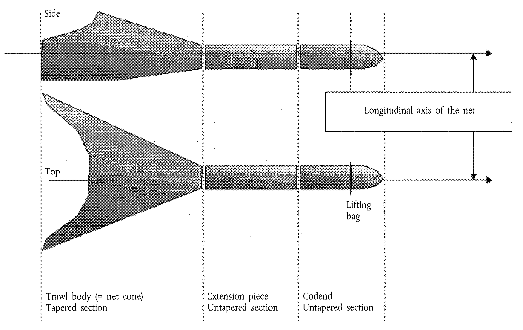
“cod-end”
means the rearmost part of a trawl with either a cylindrical or a tapering
shape, and includes the cod-end sensu stricto and the lengthening piece;
“cod-end sensu
stricto” means a cod-end that is made up of one or more pieces of netting
of the same mesh size attached to one another along their sides in the axis of
the trawl by a lacing;
“codline”
has the meaning given to that expression by Regulation 47;
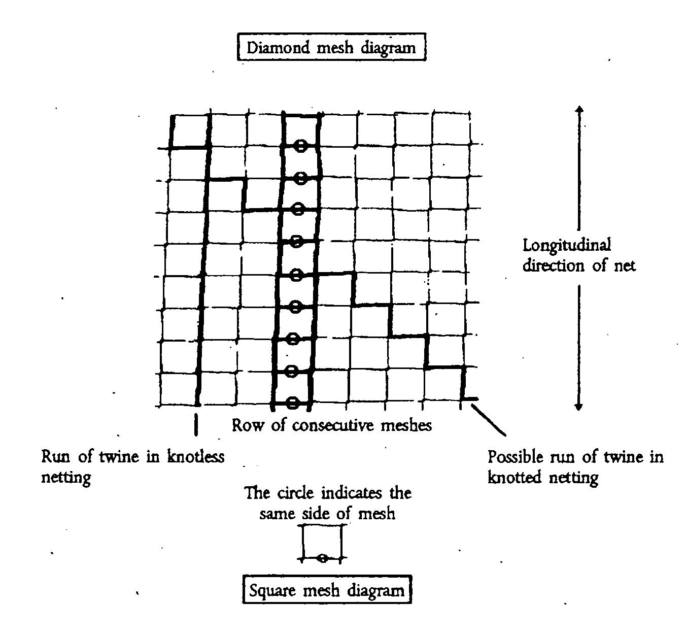
“diamond mesh” means
a mesh as shown in figure 1 of Schedule 7, composed of 4 bags of the same
length where the 2 diagonals of the mesh are perpendicular and one diagonal is
parallel to the longitudinal axis of the net as shown in figure 2 of Schedule 7;
“entangling net”
means sea fishing gear made up of a single piece of net fixed to the bottom of
the sea;
“flapper” has
the meaning given to that expression by Regulation 53;
“lacing rope”
means a rope running lengthways along the join between 2 pieces of netting in
the direction of the axis of the trawl;
“lengthening piece”
means netting consisting of one or more pieces of netting located just in front
of the cod-end sensu stricto;
“lifting strap”
has the meaning given to that expression by Regulation 49;
“Log Book
Regulations” means the Sea Fisheries (Log Books and Landing Declarations)
(Jersey) Regulations 2007;
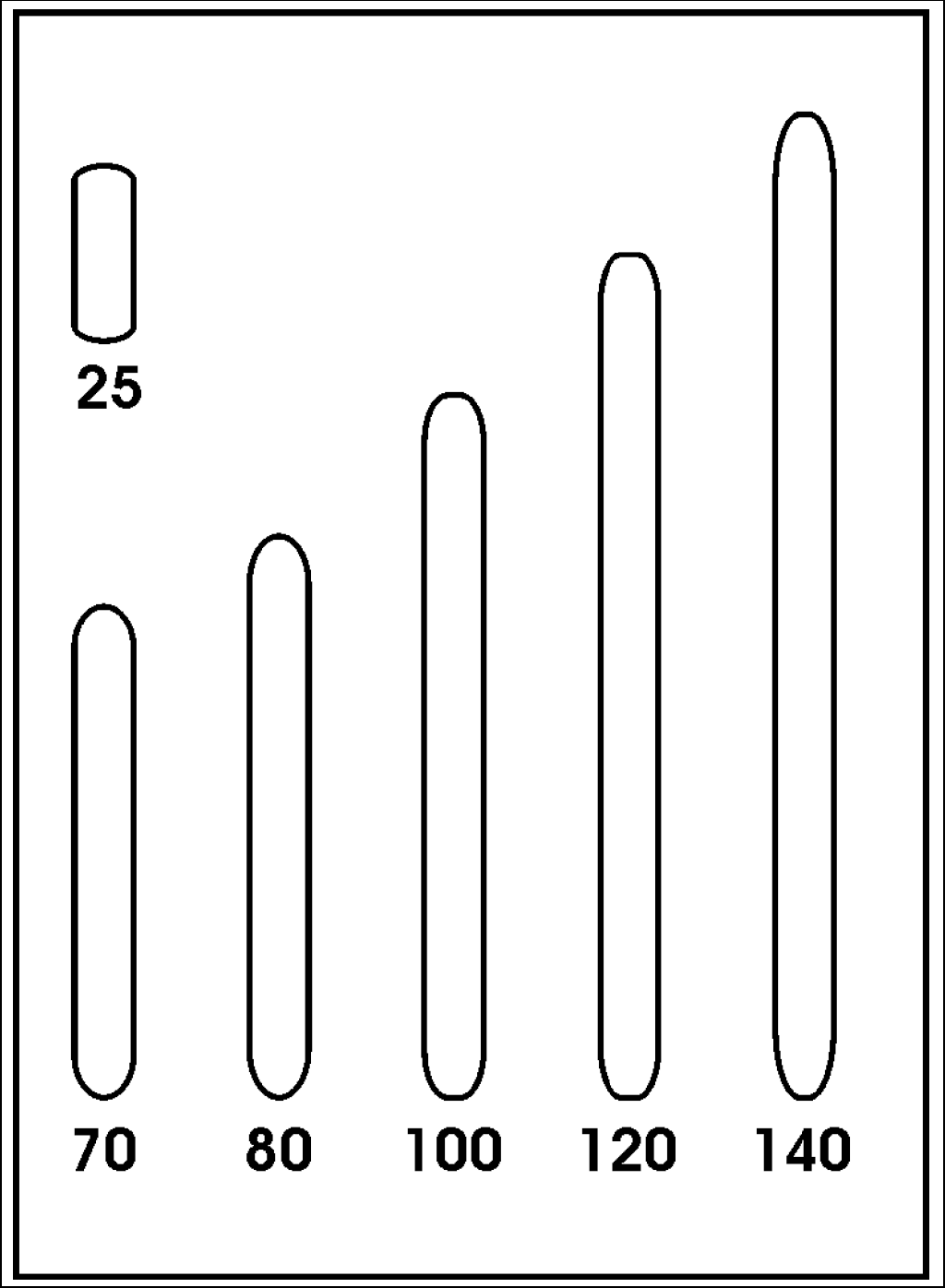
“mesh size” means –
(a) in
respect of a mesh of knotted netting, the longest distance between 2 opposite
knots in the same mesh when fully extended as shown in Schedule 6;
(b) in
respect of a mesh of knotless netting, the inside distance between the opposite
joints in the same mesh when fully extended along its longest possible axis;
“mobile gear” –
(a) means
fishing gear for which the catch operation requires an active movement of the
gear;
(b) includes
all types of –
(i) towed
gear;
(ii) dredge;
(iii) encircling
gear;
(iv) trawl;
(v) seine;
(vi) draw
net; and
(vii) any similar
towed net;
(c) does
not include a net that is operated by being pushed by hand by an individual who
is standing on the seabed;
“passive gear” means fishing gear for
which the catch operation does not require an active movement of the gear, and
includes –
(a) a
gillnet;
(b) an
entangling net;
(c) a trammel
net; and
(d) any
equipment attached to the gear, including an anchor, line or float;
“round strap”
has the meaning given to that expression by Regulation 51;
“scallop”
means a number of the species Pecten maximus;
“sieve netting”
has the meaning given to that expression by Regulation 55;
“square mesh” means a quadrilateral mesh
composed of 2 sets of parallel bars of the same length, where 1 set is parallel
to, and the other is at right angles to, the longitudinal axis of the net;
“square-meshed
netting” means a construction of netting mounted so that of the 2 sets of
parallel lines formed by the mesh bars, one set is parallel to, and the other
at right angles to, the long axis of the net;
“strengthening bag”
has the meaning given to that expression by Regulation 43;
“strengthening rope”
has the meaning given to that expression by Regulation 57;
“torquette”
has the meaning given to that expression by Regulation 59;
“trammel net”
means a net made up of 2 or more pieces of net hung jointly in parallel on a
single headline and fixed to the bottom of the sea;
“trawl”
includes a Danish seine or similar towed net.[1]
(2) References
in these Regulations to the use of a net means the use of the net for the
purpose of catching sea fish.[2]
2 [3]
Part 2[4]
Use of mobile gear and passive gear
Division 1 – mobile gear
3 Restrictions
on towing or using mobile gear
(1) It
is prohibited to tow or use mobile gear within an area of the sea described in
Schedule 1A.
(2) It
is prohibited to tow or use mobile gear within an area of the sea described in
column 1 of the table in Schedule 1B (the
“seasonally restricted sea areas”) during the period of each
calendar year in the corresponding row in column 2 of that table.
(3) The
Minister may by Order amend the seasonally restricted sea areas and periods of
the calendar year specified in Schedule 1B.
4 Restriction
on trawl nets
It is prohibited to use a
trawl net with a mesh size of less than 80 millimetres.
5 Restrictions
on towed nets
(1) It is prohibited to use
at the same time a combination of towed nets of different mesh sizes.
(2) If a fishing boat has
towed nets on board that are not being used and that have a mesh size of less
than 80 millimetres, the master of that boat must ensure that –
(a) the
nets that are not being used and their accompanying weights and sea fishing
gear are disconnected from their trawl boards and towing and hauling wires and
ropes; and
(b) any
such nets that are on or above deck are securely lashed to some part of the
superstructure of the boat.
6 Restriction
on retention and landing
(1) If
during a fishing voyage dredges are used, it is prohibited to retain on board
or land sea fish, other than bivalve molluscs, exceeding 5% of the total weight
of sea fish on board.
(2) If
during a fishing voyage trawls are used, it is prohibited to retain on board or
land shellfish exceeding 5% of the total weight of sea fish on board.
7 Prohibition
on carrying and using certain towed nets
(1) This Regulation applies
to a demersal trawl, a seine or a similar towed net with, in each
case –
(a) more
than 100 meshes in any circumference of the cod-end sensu stricto, excluding
the joinings and selvedges;
and
(b) a
mesh size that is not less than 90, but not more than 119, millimetres.
(2) But this Regulation
does not apply to a beam trawl.
(3) It is prohibited to
carry on board or use a net to which this Regulation applies.
8 Restriction
on design of certain towed nets
(1) This Regulation applies
to a towed net with a mesh size of 80 millimetres or more.
(2) Within a single cod-end
sensu stricto the number of meshes around any circumference of the cod-end must
not increase from the front end to the rear end.
(3) The number of meshes at
the point of any circumference of any extension piece or lengthening piece must
not be less than the maximum number of meshes on the circumference of the front
end of the cod-end sensu stricto.
(4) Paragraph (3) does
not apply to meshes in any selvedges.
9 Certain
towed nets to be equipped with square-meshed panels
(1) This Regulation applies
to a demersal trawl, a seine or a similar towed net with, in each case, a mesh
size that is not less than 70, but not more than 79, millimetres.
(2) The net must be
equipped with a square-meshed panel positioned anterior to the cod-end.
(3) The panel must have a
mesh size of 80 millimetres or more.
(4) The Minister may by
Order amend the mesh sizes in paragraphs (1) and (3).
10 Panels
may be inserted into other towed nets
(1) Any towed net may have
a square-meshed panel of a mesh size of 80 millimetres or more inserted
into it.
(2) Alternatively, a
demersal trawl, a seine or a similar towed net with, in each case, a mesh size
of 100 millimetres or more may be equipped with a special selectivity
device that complies with all the conditions set out in either Part 1 or
Part 2 of Schedule 4.
11 Requirements
in respect of square-meshed panels
(1) This Regulation applies
to a square-meshed panel inserted into a towed net.
(2) The panel must be
placed on the top half of the net –
(a) in front
of any extension piece; or
(b) at a
point between the front of any extension piece and the posterior of the
cod-end.
(3) The panel must not be
obstructed by internal or external attachments.
(4) The panel must be at
least 3 metres long or, if the net is towed by a vessel of less than
112 kilowatts, 2 metres long.
(5) The panel must be made
of knotless netting or of netting with non-slip knots.
(6) The panel must be
inserted in the net in such a way that its meshes remain fully open at all
times when fishing.
(7) The panel must be
constructed so that the number of meshes in the anterior row of meshes of the
panel is the same or more than the number of meshes in the posterior row of
meshes in the panel.
(8) If a panel is inserted
in an untapered portion of a net there must be no
more than 5 open diamond meshes between each panel side and the adjacent selvedges of the net.
(9) If a panel is inserted,
whether wholly or partially, into a tapered portion of a net there must be no
more than 5 open diamond meshes between the posterior row of meshes in the
panel and the adjacent selvedges in the net.
(10) In this Regulation,
“knotless netting” means netting that is composed of meshes of 4
sides of approximately equal length in which the corners of the meshes are formed
by the interweaving of the twines of 2 adjacent sides of the mesh.
12 Measurement
of mesh size of towed net
The mesh size of any square-meshed netting inserted into a towed net
must not be taken into consideration in measuring the mesh size of the net.
13 Construction
of certain cod-ends controlled
(1) It is prohibited during
a fishing voyage to carry on board or to use a towed net constructed in the
cod-end, whether wholly or partially, of single twine netting material with a
twine thickness of more than 6 millimetres.
(2) It is prohibited during
a fishing voyage to carry on board or to use a towed net constructed in the
cod-end, whether wholly or partially, of netting material consisting of
multiple twine unless –
(a) the
multiple twines are of approximately equal thickness; and
(b) the
sum of the thicknesses of the multiple twines on each side of any mesh is no
more than 8 millimetres.
(3) Paragraphs (1) and
(2) do not apply in respect of pelagic trawls.
(4) It is prohibited during
a fishing voyage to carry on board or to use a towed net the cod-end of which
is constructed, whether wholly or partially, of netting material other than
square mesh or diamond mesh.
(5) Paragraph (4) does
not apply in respect of a towed net the cod-end of which has a mesh size of
31 millimetres or less.
(6) For the purposes of
this Regulation, “multiple twine”, in respect of netting, means
netting constructed of 2 or more twines, where the twines can be separated
between knots without damage to the twine structure.
14 Restriction
on towing draw nets
(1) It
is prohibited during a fishing voyage to tow a draw net.
(2) But
a seine net may be towed if –
(a) the
net is not made of monofilament;
(b) the
net has a length of 70 metres or less;
(c) the
net has a mesh size of 55 millimetres or less; and
(d) only
lesser sand eels, greater sand eels or Corbin’s sand eels are retained on
board.
(3) The
Minister may by Order amend the conditions listed in paragraph (2).
15 Restriction
on use of draw nets to draw fish ashore
(1) Except as provided by
this Regulation, it is prohibited to use a net to draw fish ashore.
(2) A seine net may be used
to draw fish ashore if –
(a) the
net is not made of monofilament;
(b) the
net has a length of 70 metres or less;
(c) the
net has a mesh size of 55 millimetres or less; and
(d) only
lesser sand eels, greater sand eels or Corbin’s sand eels are retained.
(3) Alternatively, a seine
net may be used to draw fish ashore if –
(a) the
net has a mesh size of 100 millimetres or more;
(b) the
net is used within the period starting 1 hour before and ending 3 hours after
low water; and
(c) the
net is used –
(i) in St. Ouen’s bay; or
(ii) in
the area of the Royal bay of Grouville between the rocks known as the Tas du
Nord and the seaward end of the pier at Gorey.
(4) It is prohibited to use
a motor vehicle or a motorised winch to draw a net ashore.
16 Restriction
on carriage and use of beam trawls
(1) It
is prohibited to –
(a) use
more than 1 beam trawl from a fishing boat with a beam length of more than 6 metres;
or
(b) use a
beam trawl from a fishing boat with an engine whose power is more than 221 kW.
(2) Unless
paragraph (3) applies, it is prohibited to –
(a) carry
on a fishing boat a beam trawl, the beam length of which is more than
6 metres; or
(b) carry
a beam trawl on a fishing boat with an engine whose power is more than
221 kW.
(3) This
paragraph applies if the beam trawl, and any equipment attached to
it –
(a) is
stored on the fishing boat in such a way that no part of the trawl or equipment
is suspended over the side or the stern of the boat; and
(b) is
secured on the fishing boat in such a way that the trawl is not immediately
ready for use.
(4) The
beam length of a beam trawl is taken to be more than 6 metres if the beam
can be extended to a length more than 6 metres.
(5) The
length of a beam trawl must be measured between its extremities, which must be
taken to include any attachment to the beam.
17 Restriction
on use of scallop dredges
(1) It is prohibited for a
fishing boat to tow or use –
(a) more
than 2 beams to which scallop dredges are attached; or
(b) a
beam to which more than 6 scallop dredges are attached.
(2) It
is prohibited to use scallop dredges that have an aggregate mouth size of more
than 9.6 metres.
(3) Paragraphs (1)
and (2) do not apply to beams or scallop dredges that are stowed so that they
cannot be readily used.
(4) It is prohibited to tow
or use a scallop dredge if, where the belly of, or any side of, the bag that
comprises part of the dredge consists of rings, the smallest part of the
internal diameter of the rings measures less than 85 millimetres across.
(5) It is prohibited to tow
or use a scallop dredge if the netting used in the top of the bag that
comprises part of the dredge has a mesh size of less than 112 millimetres.
(6) It is prohibited to tow
or use a scallop dredge if the rings used in the top side of the dredge have an
internal diameter of less than 80 millimetres.
(7) It is prohibited to
carry on board or use a scallop dredge if, where the belly of, or any side of,
the bag that comprises part of the dredge consists of rings –
(a) a
device or material is attached to the dredge, in the vicinity of the rings; and
(b) the
device or material may have the effect of obstructing the movement of any
object through the diameter of the rings.
(8) In this Regulation,
“scallop dredge” means a type of fishing gear –
(a) that
is comprised of teeth, or other mechanisms, that may be used to scrape scallops
off the seabed; and
(b) that
is attached to a bag in which scallops scraped off the seabed can be collected.
(9) The Minister may by
Order amend the measurements in paragraphs (4), (5) and (6).
18 Prohibition
of encirclement of mammals with purse seines
It is prohibited when
attempting to catch sea fish to encircle a school or group of marine mammals
with purse seines.
Division 2 – passive gear
19 Prohibition
on carrying and using certain passive gear
(1) It
is prohibited during a fishing voyage to carry or use passive gear –
(a) with
a mesh size of less than 100 millimetres for fishing from a fishing boat
with a fishing boat licence, unless otherwise authorised by that fishing boat
licence under Regulation 2 of the Licensing Regulations; and
(b) with
a mesh size of less than 112 millimetres for fishing as described in Regulation
5 of the Licensing Regulations (recreational fishing or fishing operations for
the purposes of scientific investigations).
(2) In this
Regulation –
“fishing boat licence”
has the meaning given in Regulation 1 of the Licensing Regulations;
“Licensing Regulations”
means the Sea Fisheries (Licensing of
Fishing Boats) (Jersey) Regulations 2003.
20 Prohibition
on use of passive gear in certain sea depths and inshore areas
(1) It is prohibited to use
passive gear where the depth of the sea is less than 130 centimetres or another
depth that the Minister may by Order specify.
(2) It is prohibited to use
passive gear in the sea area within 200 metres of the shoreline during the
prohibited time.
(3) In
paragraph (2) –
“shoreline” means the point at which the
sea and the shore meet at any given time;
“prohibited time” means the hours of
daylight during the period 1 April to 15 October in each calendar year.
21 Restrictions
on the use of beach set nets
(1) It is prohibited to use
a beach set net.
(2) In this Regulation,
“beach set net” means passive
gear, other than pots or creels, that is put in place otherwise than from a
vessel.
22 Marking
of gillnets nets and trammel nets
It is prohibited to use a gillnet or a trammel net unless it has a
buoy attached by line to each end of the net to which is attached a separate
float that is –
(a) coloured
red and white;
(b) at
least 15 centimetres in width;
(c) at
least 25 centimetres in length; and
(d) visible
above the surface of the water.
Division 3 – general
23 Restriction
on trans-shipping
It is prohibited to trans-ship sea fish to or from a vessel if the
master of the vessel does not complete a log book in accordance with the Log
Book Regulations.
24 Attachments
to nets
Except to the extent permitted by these Regulations, it is
prohibited to use a device that obstructs or otherwise diminishes the mesh in
any part of a net.
25 Certain
processing operations prohibited
(1) It is prohibited to
carry out on board a vessel any physical or chemical processing of fish to
produce fishmeal, oil or similar products. or to trans-ship fish for such a
purpose.
(2) It is prohibited to
trans-ship fish for a purpose described in paragraph (1).
(3) Paragraphs (1) and (2)
do not apply to the processing or trans-shipment of offal, nor to the
production on board a fishing boat of surimi or fish pulp.
26 Sorting
Sorting must be carried out immediately after the catch has been
removed from the net.
Part 3[5]
determining mesh size and ASSESSING TWINE THICKNESS of fishing gear
Chapter
1 – Interpretation
27 Interpretation –
Part 3[6]
In this Part –
“mesh gauge”
means a mesh measuring gauge that has 2 jaws that automatically apply
longitudinal forces in the range of 5 to 180 Newton to a mesh, with a
precision of 1 Newton;
“N-direction”,
in respect of knotted netting, means the direction at right angles to the
general course of the netting yarn, as shown in Schedule 6;
“T-direction”
means –
(a) in
respect of knotted netting, the direction parallel to the general course of the
netting yarn, as shown in Schedule 6;
(b) in
respect of knotless netting, the direction at right angles to the N-direction;
“T90
mesh” means a diamond mesh from knotted netting, as shown in
figure 1 of Schedule 7, mounted so that the T-direction of the
netting is parallel to the longitudinal axis of the net.
Chapter
2 – EC gauges
28 Mesh
gauge and thickness gauge
A fishery officer, when conducting
a fishery inspection of fishing gear, must –
(a) to
determine the mesh size of the gear, use a mesh gauge that complies with the
technical specifications set out in Schedule 8; or
(b) to
assess the twine thickness of the gear, use a twine thickness gauge that
complies with the technical specifications set out in Schedule 9.
29 Calibration
instruments for a mesh gauge
The calibrated test weights
and calibrated test measuring plate provided for in figure 1 of Schedule 10
must be certified by the Chief Inspector of Weights and Measures appointed
under Article 2 of the Weights
and Measures (Jersey) Law 1967.
30 Testing
of a mesh gauge
The accuracy of a mesh gauge
must be verified by –
(a) inserting
the jaws of the gauge into slots of the calibrated test plate as provided for
in figure 1 of Schedule 10; and
(b) hanging
the calibrated test weights on the fixed jaw, as provided for in figure 2
of Schedule 10.
Chapter
3 – Determination of mesh size
31 Selection
of meshes in mobile gear[7]
(1) A
fishery officer, when conducting a fishery inspection of the mesh size of mobile
gear, must select a series of 20 consecutive meshes from the gear for
testing.[8]
(2) The
meshes must be chosen –
(a) in
the case of diamond and square meshes, in the direction of the longitudinal
axis of the gear; and
(b) in
the case of T90 meshes, perpendicular to the
direction of the longitudinal axis of the gear.
(3) The
fishery officer must not select meshes that are less than 3 meshes from
the selvedge, lacings, ropes or cod line when that distance is measured
perpendicular to the lacings, ropes or cod line with the net stretched in the
direction of that measurement.[9]
(4) A
fishery officer must not measure a mesh –
(a) that is
broken or has been repaired; or
(b) that
has attachments to the net fixed at the mesh.[10]
(5) Despite
paragraph (1), the meshes to be measured need not be consecutive to the
extent that the application of paragraph (3) prevents it.
32 Selection
of meshes in passive gear
(1) A
fishery officer, when conducting a fishery inspection of the mesh size of
passive gear, must select 20 meshes from the gear for testing.
(2) If
there are different mesh sizes in the gear, the meshes must be selected from
the part of the gear that has the smallest meshes.
(3) A
fishery officer must not select meshes –
(a) that
are at the top, bottom or side of a net selvedge;
(b) that
are within 3 meshes of lacings or ropes; or
(c) that
are broken or have been repaired.[11]
33 The
preparation and operation of mesh gauges[12]
A fishery officer, when
carrying out a fisheries inspection of the mesh size of fishing gear,
must –
(a) prepare,
in accordance with Schedule 11, the mesh gauge to be used; and
(b) operate
the gauge in accordance with Schedule 12.
34 Operation
of the mesh gauge for measuring diamond and T90 meshes
(1) This
Regulation specifies how a fishery officer must measure a diamond or T90 mesh.[13]
(2) In
knotless netting when the N-direction cannot be determined, the officer must measure
the longest axis of the mesh.
(3) In
other cases, the netting must be stretched in the N-direction of the meshes and
the officer must measure the mesh as shown in Schedule 12.
35 Operation
of the mesh gauge for measuring square meshes
(1) This
Regulation specifies how a fishery officer must measure a square mesh panel.[14]
(2) The
netting must be stretched first in one diagonal direction and then in the other
diagonal direction of the mesh, as shown in Schedule 13.
(3) The
officer must then follow the procedure laid down in Schedule 11 to measure
each diagonal direction of the square mesh.
36 Measurement
conditions[15]
A fishery officer, when
carrying out a fisheries inspection of the mesh size of fishing gear must
measure a mesh when it is wet and not frozen.
37 Measurement
of the size of each selected mesh
(1) For
the purposes of a fishing inspection of the meshes of fishing gear, the size of
each mesh is the distance between the outside edges of the jaws of the mesh
gauge at the point where its movable jaw is stopped.
(2) However,
if there is a difference in measurement between the diagonals of an individual
square mesh, the larger diagonal is to be used.
37A Determination of
the mesh size of a net
For the purposes of a
fishing inspection of the mesh size of fishing gear, the mesh size of the gear
is the mean value, as displayed by the gauge, of the series of 20 selected
meshes of the gear.
37B Determination of
the mesh size in case of disputes
(1) This
Regulation applies if the master of a fishing boat disputes the mesh size of
any fishing gear on the boat as determined under Article 37A.
(2) The
fishery officer must select and measure, in accordance with Articles 31 to
37, 20 meshes in another part of the gear.[16]
(3) The
mesh size of the gear is the mean value, displayed by the mesh gauge, of all
the 40 meshes measured.
(4) For
the purpose of this Regulation, the displayed result of the mesh gauge is
final.
Chapter
4 – Assessing twine thickness
37C General
provisions on the selection of twines
(1) A
fishery officer, when testing the thickness of the twine of fishing gear as
part of a fishery inspection of the gear, must select meshes from a part of the
gear that is subject to a maximum permitted twine thickness.
(2) The
officer must not select a twine from a mesh that is broken or has been
repaired.
37D Selection of twine
in diamond mesh netting
(1) If
the fishing gear to be tested has diamond mesh netting, the fishery officer
must select the twines to be tested in accordance with paragraph (2).[17]
(2) In
the case of –
(a) single
twine netting, the twine on the opposite sides of 10 meshes must be
selected; or
(b) double
twine netting, each strand of twine on opposite sides of 5 meshes must be
selected,
as shown by Schedule 13.
37E Selection of
twines in square mesh netting
(1) If
the fishing gear to be tested has square mesh, the fishery officer must select
the twines to be tested in accordance with paragraph (2).[18]
(2) In
the case of –
(a) single
twine netting, the twine on one side of 20 meshes must be selected, with
the same side being selected in each mesh; or
(b) double
twine netting, each strand of twine on one side of 10 meshes must be
assessed, with the same side being selected in each mesh,
as shown by Schedule 13.
37F Selection of
the twine thickness gauge[19]
A fishery officer, to test
the thickness of twine in fishing gear as part of a fishery inspection, must
use a gauge that has a circular hole with a diameter equal to the maximum twine
thickness permitted for the part of the gear to be considered.
37G Assessment
conditions[20]
A fishery officer, when
conducting a fishery inspection of fishing gear as part of a fishery
inspection, must not test the thickness of a twine in the gear when the twine
is frozen.
37H Assessment of the
thickness of each selected twine[21]
A fishery officer, when
testing the thickness of a twine in fishing gear as part of a fishery
inspection of the gear, must note the twine as a negative if –
(a) the
thickness of the twine prevents the closure of the jaws of the gauge; or
(b) the
twine does not pass easily through the hole when the jaws are closed.
37I Assessing
twine thickness
(1) This
Regulation applies if a fishery officer notes more than 5 negative
assessments of the 20 twines selected under Regulation 37C.[22]
(2) The
fishery officer must select and assess a further 20 twines in accordance
with Regulations 37C to 37H.[23]
(3) If
the fishery officer notes more than 10 negative of the total
40 twines selected the twine thickness is to be taken to have exceeded the
maximum twine thickness permitted for that part of the fishing gear.[24]
37J Assessment
of twine thickness in case of disputes
(1) This
Regulation applies if the master of a fishing boat disputes the twine thickness
of any fishing gear on the boat as assessed under Article 37I.
(2) The
fishery officer must select and assess 20 different twines in the same
part of the fishing gear.[25]
(3) If
more than 5 negative assessments of the total 20 twines selected are
noted, the twine thickness is to be taken as exceeding the maximum twine
thickness permitted for that part of the fishing gear.
(4) For
the purpose of this Regulation, that assessment is final.
PART 4[26]
PART 4A[27]
PART 5
ATTACHMENT OF DEVICES TO NETS
38 Bottom-side
chafer
(1) This
Regulation applies to bottom-side chafers.
(2) They
may be formed of any material.
(3) More
than 1 chafer may be attached to a trawl at the same time.
(4) Chafers
may overlap.
(5) Chafers
attached to a trawl shall be attached to the outside of the trawl on the lower
half of any part of the trawl.
(6) Chafers
attached to a trawl shall not be fastened to the trawl except at their front
and side edges.
(7) If
a strengthening bag or chafing piece is used in respect of a trawl, a chafer
attached to the trawl shall be attached outside the strengthening bag or
chafing piece in the manner specified in paragraphs (5) and (6).
39 Top-side
chafer
The use of either of 2
types of top-side chafer, designated for the purpose of these Regulations type
A and type B, is permitted.
40 Type
A top side chafer
(1) This
Regulation applies to a type A top-side chafer.
(2) It
may be formed of any rectangular piece of netting that has a mesh size equal to
at least that of the cod-end.
(3) The
width of the chafer shall be at least 1½ times the width of the cod-end
which is covered.
(4) Those
widths shall be measured perpendicular to the long axis of the cod-end.
(5) The
chafer shall not be attached to the trawl except by its forward and lateral
edges to the upper half of the outside of the cod-end.
(6) If
a lifting strap is fitted to the cod-end the chafer shall be fastened in such a
manner that it does not extend more than 4 meshes forward of the rear lifting
strap.
(7) If
a lifting strap is not fitted the chafer shall be fastened in such a manner
that it does not cover more than the last rear third of the cod-end.
(8) In
both cases under paragraphs (6) and (7) the top-side chafer shall end not
less than 4 meshes in front of the codline.
41 Type
B top side chafer
(1) This
Regulation applies to a type B top-side chafer.
(2) It
may be formed of any rectangular piece of netting made of twine that has the
same diameter as that of the cod-end.
(3) The
netting must have a mesh size equal to twice that of the cod-end.
(4) It
may completely cover the upper half of the cod-end sensu stricto.
(5) It
shall not be attached to the trawl except by its 4 edges and in such a way
that, at the points of attachment, the side of each mesh coincides with 2 sides
of the meshes of the cod-end.
42 Restrictions
on use of top-side chafers
(1) It
is prohibited to use more than one top-side chafer at the same time.
(2) It
is prohibited to use a top-side chafer together with a strengthening bag.
(3) Paragraph (2)
does not apply to a trawl with a mesh size of 60 millimetres or less.
43 Strengthening
bag defined
(1) For
the purpose of these Regulations a strengthening bag is a cylindrical piece of
netting that completely surrounds the cod-end of a trawl.
(2) It
may be attached to the cod-end at intervals.
44 Regulation
of strengthening bags
(1) Except
as provided by paragraph (2), it is prohibited to use a strengthening bag
unless it is at least the same length and width as that part of the cod-end to
which it is attached.
(2) A
strengthening bag smaller than the dimensions of the cod-end to which it is
attached may be attached to a trawl with a mesh size of 60 millimetres or less.
(3) Except
as provided by paragraph (4), it is prohibited to use more than one
strengthening bag on a trawl.
(4) Two
strengthening bags may be attached to a trawl with a mesh size of
60 millimetres or less.
(5) It
is prohibited to use a strengthening bag on a trawl unless the mesh size of the
bag is at least twice that of the cod-end to which it is attached, and, if a second
strengthening bag is used, its mesh size is at least 120 millimetres.
(6) It
is prohibited to use a strengthening bag that extends forward of the cod-end to
which it is attached.
(7) If
a strengthening bag is constructed of sections of cylindrical netting, the
sections must not overlap by more than 4 meshes at the points of attachment.
(8) A
strengthening bag attached to a trawl with a mesh size greater than 60
millimetres shall not extend more than 2 metres in front of the rear lifting
strap.
45 Chafing
or protection piece defined
(1) A
chafing or protection piece is a short cylindrical piece of netting at the
points of attachment of the lifting strap.
(2) It
has the same circumference as the cod-end or any strengthening bag that
surrounds the cod-end.
46 Regulation
of chafing or protection pieces
(1) It
is prohibited to use a chafing piece if a lifting strap is not attached to the
cod-end.
(2) It
is prohibited to use a chafing piece that is more than one metre long.
(3) A
chafing piece may only be attached in front of and behind each lifting strap.
(4) The
mesh size of a chafing piece must be at least equal to that of the cod-end.
(5) If
the circumference of a chafing piece is to be compared with the circumference
of a cod-end or strengthening bag they shall be compared when the chafing piece
and the cod-end or strengthening bag are each stretched with the same force.
47 Codline defined
(1) A
codline is a rope that makes it possible to close the
rear of a cod-end or of a strengthening bag.
(2) It
works either by means of a knot that can be easily loosened or by means of a
mechanical device.
48 Regulation
of codlines
(1) A
codline must be attached at a distance that is not
more than one metre from the rear meshes of the cod-end, which may be folded
back into the cod-end.
(2) If
a torquette is attached the codline
must be passed through the rearmost meshes of the cod-end.
(3) More
than one codline may be used on a trawl.
(4) A
codline must not enclose a bottom-side chafer or
top-side chafer.
49 Lifting
strap defined
(1) A
lifting strap is a piece of rope or wire loosely encircling the circumference
of a cod-end or of any strengthening bag.
(2) It
is attached to the cod-end or strengthening bag by means of loops or rings.
(3) More
than one lifting strap may be used at any time.
50 Regulation
of lifting straps
(1) It
is prohibited to use a lifting strap that has a length that is less than 40% of
the circumference of the cod-end it encircles.
(2) Paragraph (1)
does not apply in respect of the lifting strap nearest to the codline, which may be shorter.
(3) For
the purpose of this Regulation the circumference of a cod-end shall be measured
as the product of the number of meshes in the circumference of the cod-end
multiplied by its mesh size.
51 Round
straps defined
(1) A
round strap is a ring-shaped rope that encircles the cod-end or any
strengthening bag and is attached to it.
(2) Round
straps encircle the cod-end or strengthening bag at regular intervals.
52 Regulation
of round straps
(1) It
is prohibited to use a round strap that has a length that is less than 40% of
the circumference of the cod-end it encircles.
(2) Paragraph (1)
does not apply in respect of the rearmost round strap on a cod-end (“the
back strap”) if it is attached not more than 2 metres from the codline meshes, measured when the meshes are stretched lengthways.
(3) For
the purpose of this Regulation the circumference of a cod-end shall be measured
as the product of the number of meshes in the circumference of the cod-end
multiplied by its mesh size.
(4) The
distance separating 2 successive round straps shall be not less than one
metre.
(5) A
round strap may encircle a strengthening bag.
(6) It
must not encircle a top-side or bottom-side chafer.
53 Flapper
defined
(1) A
flapper is a piece of netting fastened inside a trawl in such a way that it
allows catches to pass from the front to the rear of the trawl but limits their
return.
(2) It
has a mesh size at least equal to that of the cod-end of the trawl.
54 Flappers
regulated
(1) A
flapper shall be attached at its front end and may be attached at its lateral
edges inside the cod-end or in front of the cod-end.
(2) The
distance from the point of forward attachment of the flapper to the rear end of
the cod-end shall be at least 3 times the length of the flapper.
55 Sieve
netting defined
Sieve netting is a piece
of netting with a mesh size that is at least twice the mesh size of the
cod-end.
56 Sieve
netting regulated
(1) When
sieve netting is used it shall be attached inside the trawl in front of the
cod-end.
(2) It
shall not extend into the cod-end by more than 1/3 of the length of the
cod-end.
(3) It
may be attached to the trawl at all edges.
(4) Two
pieces of sieve netting may be used at the same time if they are attached to
the upper and lower halves of the trawl respectively and do not overlap at any
point.
57 Strengthening
rope defined
A strengthening rope is
any rope, other than a lacing rope, that is attached to any part of a trawl.
58 Use
of strengthening rope regulated
It is prohibited to
attach a strengthening rope inside a cod-end.
59 Torquette defined
(1) A
torquette is a piece of netting fixed inside the
cod-end at its rear end.
(2) It
may be folded back into the cod-end.
60 Torquettes regulated[28]
(1) The
mesh size of a torquette shall not be less than the
mesh size of the cod-end in which it is fixed.
(2) A
torquette shall not be attached except at its forward
edge.
(3) It
shall be attached no further forward than the last 5 meshes of the cod-end.
(4) It
shall not extend backwards more than one metre from the rear of the last meshes
of the cod-end.
61 Median
lacing to form a trouser cod-end
In order to build a
trouser cod-end, meshes may be laced together by joining lengthways the upper
and lower halves of a cod-end.
PART 6
MISCELLANEOUS
61A Maximum fines[29]
(1) For
the purposes of Article 4(1) of the Law, the maximum fine to which a
person shall be liable if he or she is found guilty of an offence against that
Article in relation to a contravention of a Regulation, set out in these
Regulations, that is made under Article 2 of the Law, shall
be –
(a) if
the person has not previously been found guilty of an offence against Article 4
of the Law in relation to a contravention of that Regulation –
£20,000; or
(b) if
the person has previously been found guilty of an offence against Article 4
of the Law in relation to a contravention of that Regulation –
£40,000.
(2) For
the purposes of Article 5(5) of the Law, the maximum fine to which a
person shall be liable if he or she is found guilty of an offence against that
Article in relation to a contravention of a Regulation, set out in these
Regulations, that is made under Article 5 of the Law, shall
be –
(a) if
the person has not previously been found guilty of an offence against Article 5
of the Law in relation to a contravention of that Regulation –
£20,000; or
(b) if
the person has previously been found guilty of an offence against Article 5
of the Law in relation to a contravention of that Regulation –
£40,000.
62 Citation
These Regulations may be
cited as the Sea Fisheries (Trawling, Netting and Dredging) (Jersey)
Regulations 2001.
Schedule 1[30]
Schedule 1A[31]
(Regulation 3(1))
Restricted sea areas
1. The
waters at Les Écréhous situated within
the area denoted by the following co-ordinates (using the World Geodetic
System 1984 (‘WGS84’) reference
system) beginning with co-ordinate number 1 and joining in the sequence
given, in a series of straight lines, co-ordinates 1 to 8 and then joining
co-ordinate 8 to co-ordinate 1 –
|
Co-ordinate
number
|
Latitude (WGS84)
|
Longitude (WGS84)
|
|
1
|
49°18.146N
|
001°55.000W
|
|
2
|
49°17.630N
|
001°54.200W
|
|
3
|
49°16.391N
|
001°54.583W
|
|
4
|
49°16.076N
|
001°54.827W
|
|
5
|
49°16.350N
|
001°56.250W
|
|
6
|
49°16.550N
|
001°57.855W
|
|
7
|
49°17.802N
|
001°58.490W
|
|
8
|
49°18.200N
|
001°57.400W
|
2. The
waters at Les Minquiers situated within the area
denoted by following the co-ordinates (using the WGS84
reference system) beginning with co-ordinate number 1 and joining in the sequence
given, in a series of straight lines, co-ordinates 1 to 11 and then
joining co-ordinate 11 to co-ordinate 1 –
|
Co-ordinate
number
|
Latitude (WGS84)
|
Longitude (WGS84)
|
|
1
|
49°00.221N
|
002°10.900W
|
|
2
|
49°00.102N
|
002°07.196W
|
|
3
|
48°59.349N
|
002°07.199W
|
|
4
|
48°59.357N
|
002°05.604W
|
|
5
|
48°58.199N
|
002°02.800W
|
|
6
|
48°58.029N
|
002°02.699W
|
|
7
|
48°57.299N
|
002°03.708W
|
|
8
|
48°57.293N
|
002°06.195W
|
|
9
|
48°56.598N
|
002°06.198W
|
|
10
|
48°56.601N
|
002°10.900W
|
|
11
|
49°00.220N
|
002°10.900W.
|
3. The
area of sea within St. Brelade’s bay bounded on the seaward side by
a straight line beginning with co-ordinate 1 and joining in a straight
line to co-ordinate 2 –
|
|
|
|
|
1
|
49°10.523’N
|
002°12.637’W
|
|
2
|
49°10.162’N
|
002°11.373’W
|
4. The
area of sea within St. Aubin’s bay bounded on the seaward side by a
straight line beginning with co-ordinate 1 and joining in a straight line
to co-ordinate 2 –
|
|
|
|
|
1
|
49°10.4912’N
|
002°09.8365’W
|
|
2
|
49°10.5536’N
|
002°07.6455’W
|
5. The
area of sea within the small roads in St. Aubin’s bay bounded on the
seaward side by a straight line beginning with co-ordinate 1 and joining
in the sequence given, in a series of straight lines, co-ordinates 1 to
5 –
|
|
|
|
|
1
|
49°10.225’N
|
002°07.390’W
|
|
2
|
49°10.109’N
|
002°07.491’W
|
|
3
|
49°09.957’N
|
002°07.282’W
|
|
4
|
49°09.990’N
|
002°06.951’W
|
|
5
|
49°10.071’N
|
002°06.681’W
|
6. The
area of sea within Fliquet bay bounded on the seaward
side by a straight line beginning with co-ordinate 1 and joining in a
straight line to co-ordinate 2 –
|
|
|
|
|
1
|
49°13.335’N
|
002°00.650’W
|
|
2
|
49°14.0738’N
|
002°01.2833’W
|
7. The
area of sea to the east of Jersey bounded on the seaward side by straight lines
beginning with co-ordinate 1 and joining in the sequence given, in a
series of straight lines, co-ordinates 1 to 9 –
|
|
|
|
|
1
|
49°09.753’N
|
002°01.897’W
|
|
2
|
49° 08.225’N
|
002° 00.171’W
|
|
3
|
49°08.831’N
|
001°58.871’W
|
|
4
|
49° 09.771’N
|
001° 58.797’W
|
|
5
|
49°10.130’N
|
001°59.231’W
|
|
6
|
49°10.963’N
|
001°59.852’W
|
|
7
|
49°12.022’N
|
002°00.598’W
|
|
8
|
49°12.857’N
|
002°00.478’W
|
|
9
|
49°13.335’N
|
002°00.650’W
|
8. The
area of sea to the north of Jersey bounded on the seaward side by straight
lines beginning with co-ordinate 1 and joining in the sequence given, in a
series of straight lines, co-ordinates 1 to 13 –
|
|
|
|
|
1
|
49°15.500’N
|
002°14.800’W
|
|
2
|
49°15.493’N
|
002° 14.883’W
|
|
3
|
49°15.615’N
|
002° 14.975’W
|
|
4
|
49°15.815’N
|
002°14.170’W
|
|
5
|
49°15.815’N
|
002° 12.250’W
|
|
6
|
49°15.370’N
|
002° 11.170’W
|
|
7
|
49°15.840’N
|
002° 09.400’W
|
|
8
|
49°16.000’N
|
002° 07.830’W
|
|
9
|
49°15.820’N
|
002° 06.150’W
|
|
10
|
49°15.200’N
|
002° 03.100’W
|
|
11
|
49°14.595’N
|
002° 01.730’W
|
|
12
|
49°14.150’N
|
002° 01.180’W
|
|
13
|
49°13.967’N
|
002°01.566’W
|
9. The
area of sea to the south and east of Jersey bounded on the seaward side by
straight lines beginning with the co-ordinate 1 and joining in the
sequence given, in a series of straight lines, co-ordinates 1 to
18 –
|
|
|
|
|
1
|
49°10.071’N
|
002°06.681’W
|
|
2
|
49°09.990’N
|
002°06.951’W
|
|
3
|
49°09.006’N
|
002°06.141’W
|
|
4
|
49°08.610’N
|
002°05.140’W
|
|
5
|
49°08.100’N
|
002°01.700’W
|
|
6
|
49°07.820’N
|
001°59.040’W
|
|
7
|
49°07.743’N
|
001°55.012’W
|
|
8
|
49°08.702’N
|
001°55.400’W
|
|
9
|
49°08.713’N
|
001°56.012’W
|
|
10
|
49°09.849’N
|
001°55.955’W
|
|
11
|
49°09.851’N
|
001°57.155’W
|
|
12
|
49°08.782’N
|
001°57.211’W
|
|
13
|
49°08.800’N
|
001°57.616’W
|
|
14
|
49°10.590’N
|
001°58.997’W
|
|
15
|
49°10.980’N
|
001°59.535’W
|
|
16
|
49°12.022’N
|
002°00.598’W
|
|
17
|
49°12.857’N
|
002°00.478’W
|
|
18
|
49°13.335’N
|
002°00.650’W
|
10. The
area of sea to the south of Jersey, west of St. Aubin’s bay, bounded
on the seaward side by straight lines beginning with the co-ordinate 1 and
joining in the sequence given, in a series of straight lines, co-ordinates 1
to 5 –
|
|
|
|
|
1
|
49°10.494’N
|
002°09.843’W
|
|
2
|
49°10.639’N
|
002°09.459’W
|
|
3
|
49°10.011’N
|
002°09.120’W
|
|
4
|
49°09.850’N
|
002°09.688’W
|
|
5
|
49°09.909’N
|
002°10.076’W
|
Schedule 1B[32]
(Regulation 3(2))
Seasonally restricted sea areas
|
Column 1
|
Column
2
|
|
Area
description
|
Period
of restriction
|
|
The waters off the
north-west Dirouilles situated within the area
denoted by following the co-ordinates beginning with co-ordinate 1 and
joining in the sequence given, in a series of straight lines, co-ordinates 1
to 4 and then joining co-ordinate 4 to co-ordinate 1 –
|
The start of 1 April to the
end of 31 July
|
|
Co-ordinate
number
|
Latitude (WGS84)
|
Longitude (WGS84)
|
|
|
1
|
49°22.100’N
|
002°05.000’W
|
|
|
2
|
49°20.000’N
|
002°05.000’W
|
|
|
3
|
49°20.000’N
|
002°09.600’W
|
|
|
4
|
49°22.100’N
|
002°09.600’W
|
|
|
|
|
|
The waters south of the Frouquier Aubert buoy situated within the area denoted by
following the co-ordinates beginning with co-ordinate 1 and joining in the
sequence given, in a series of straight lines, co-ordinates 1 to 4 and then
joining co-ordinate 4 to co-ordinate 1 –
|
The start of 1 April to
the end of 31 July
|
|
Co-ordinate
number
|
Latitude (WGS84)
|
Longitude (WGS84)
|
|
|
1
|
49°05.100’N
|
001°55.000’W
|
|
|
2
|
49°02.500’N
|
001°55.000’W
|
|
|
3
|
49°02.500’N
|
002°03.200’W
|
|
|
4
|
49°05.100’N
|
002°03.200’W
|
|
|
|
|
|
The waters off the north
of Jersey situated within the area denoted by following the co-ordinates
beginning with co-ordinate 1 and joining in the sequence given, in a series
of straight lines, co-ordinates 1 to 8 and then joining co-ordinate 8 to
co-ordinate 1 –
|
The start of July 1 to
the end of 30 September
|
|
Co-ordinate
number
|
Latitude (WGS84)
|
Longitude (WGS84)
|
|
|
1
|
49°17.000’N
|
002°13.200’W
|
|
|
2
|
49°17.000’N
|
002°06.625’W
|
|
|
3
|
49°15.870’N
|
002°06.625’W
|
|
|
4
|
49°16.000’N
|
002°07.830’W
|
|
|
5
|
49°15.840’N
|
002°09.400’W
|
|
|
6
|
49°15.370’N
|
002°11.170’W
|
|
|
7
|
49°15.815’N
|
002°12.250’W
|
|
|
8
|
49°15.815’N
|
002°13.200’W
|
|
|
|
|
|
The waters off the west
of Jersey situated within the area denoted by following the co-ordinates
beginning with co-ordinate 1 and joining in the sequence given, in a series
of straight lines, co-ordinates 1 to 4 and then joining co-ordinate 4 to
co-ordinate 1 –
|
The start of April 1 to
the end of September 30
|
|
Co-ordinate
number
|
Latitude (WGS84)
|
Longitude (WGS84)
|
|
|
1
|
49°13.125’N
|
002°18.500’W
|
|
|
2
|
49°12.400’N
|
002°15.375’W
|
|
|
3
|
49°10.625’N
|
002°15.375’W
|
|
|
4
|
49°10.625’N
|
002°16.900’W
|
|
|
|
|
|
The waters off the
south-west of Jersey situated within the area denoted by following the
co-ordinates beginning with co-ordinate 1 and joining in the sequence given,
in a series of straight lines, co-ordinates 1 to 4 and then joining
co-ordinate 4 to co-ordinate 1 –
|
The start of April 1 to
the end of September 30
|
|
Co-ordinate
number
|
Latitude (WGS84)
|
Longitude (WGS84)
|
|
|
1
|
49°10.625’N
|
002°15.375’W
|
|
|
2
|
49°10.450’N
|
002°13.950’W
|
|
|
3
|
49°10.000’N
|
002°13.950’W
|
|
|
4
|
49°10.000’N
|
002°15.350’W
|
|
|
|
|
|
The waters off the south
of Jersey situated within the area denoted by following the co-ordinates
beginning with co-ordinate 1 and joining in the sequence given, in a series
of straight lines, co-ordinates 1 to 4 and then joining co-ordinate 4 to
co-ordinate 1 –
|
The start of April 1 to
the end of September 30
|
|
Co-ordinate
number
|
Latitude (WGS84)
|
Longitude (WGS84)
|
|
|
1
|
49°10.010’N
|
002°09.120’W
|
|
|
2
|
49°10.504’N
|
002°09.386’W
|
|
|
3
|
49°10.540’N
|
002°08.150’W
|
|
|
4
|
49°10.010’N
|
002°07.460’W
|
|
Schedule 2[33]
Schedule 3[34]
Schedule 4[35]
(Regulation 10(2))
Special selectivity devices
PART 1
Exit window (model 1)
1. Two
exit windows with plastic coated, fully opened diamond meshes may be attached
to the cod-end of trawls and Danish seines.
2. The
mesh opening shall be no less than 105 millimetres.
3. An
exit window shall be attached with a separate piece of netting (between the
ordinary diamond meshes and the meshes of the exit window).
4. The
mesh size of the separate netting shall be identical to the bar length of the
exit windows times the square root of 2 (1.414213562373).
5. The
exit window shall be attached on both sides of the cod-end.
6. The
distance between the rear end of the cod-end and the window shall be 40
to 50 centimetres.
7. The
length of the window shall be 80 % of the total length of the cod-end and the
height of the window shall be 50 centimetres.
8. An
exit window shall be mounted in a way that gives an opening between the upper
and lower seams of the window of 15 to 20 centimetres.
PART 2
Exit Window (model 2)
1. There
shall be 2 windows.
2. The
windows shall be rectangular sections of netting in the cod-end.
3. Each
window shall have a minimum width of 45 cm along its entire length.
4. Each
window shall have a minimum length of 3.5 m measured along its sides.
5. The
meshes in the windows shall have a minimum size of 105 millimetres.
6. They
shall be square meshes, i.e. all 4 sides of the window netting will be cut by
all bars.
7. The
netting shall be mounted such that the bars run parallel and perpendicular to
the length of the cod-end.
8. The
window width shall be 8 open square meshes.
9. The
length shall be between 57 and 62 square meshes.
10. The
cod-end shall be divided into upper and lower panels by selvedges
running down the port and starboard sides.
11. The
2 windows shall be located in the lower panel, immediately adjacent to and
below the selvedges.
12. The
windows shall terminate a minimum of 2 metres and a maximum of 2.5 metres from
the codline.
13. The
forward end of the window shall be joined to 8 meshes’ width of the
normal cod-end netting.
14. One
side shall join to the selvedge or be joined immediately adjacent to the
selvedge and the other side shall be joined to the normal cod-end lower panel
netting following a straight line of meshes all knots cut.
15. All
parts of the cod-end shall conform to a minimum mesh size of 105 millimetres.
Schedule 5[36]
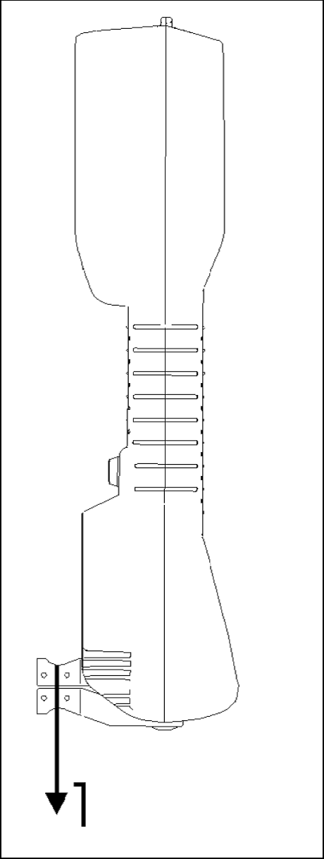
Schedule 6[37]
(Regulation 27)
Mesh size and N-direction
and T-direction of netting twine
Figure
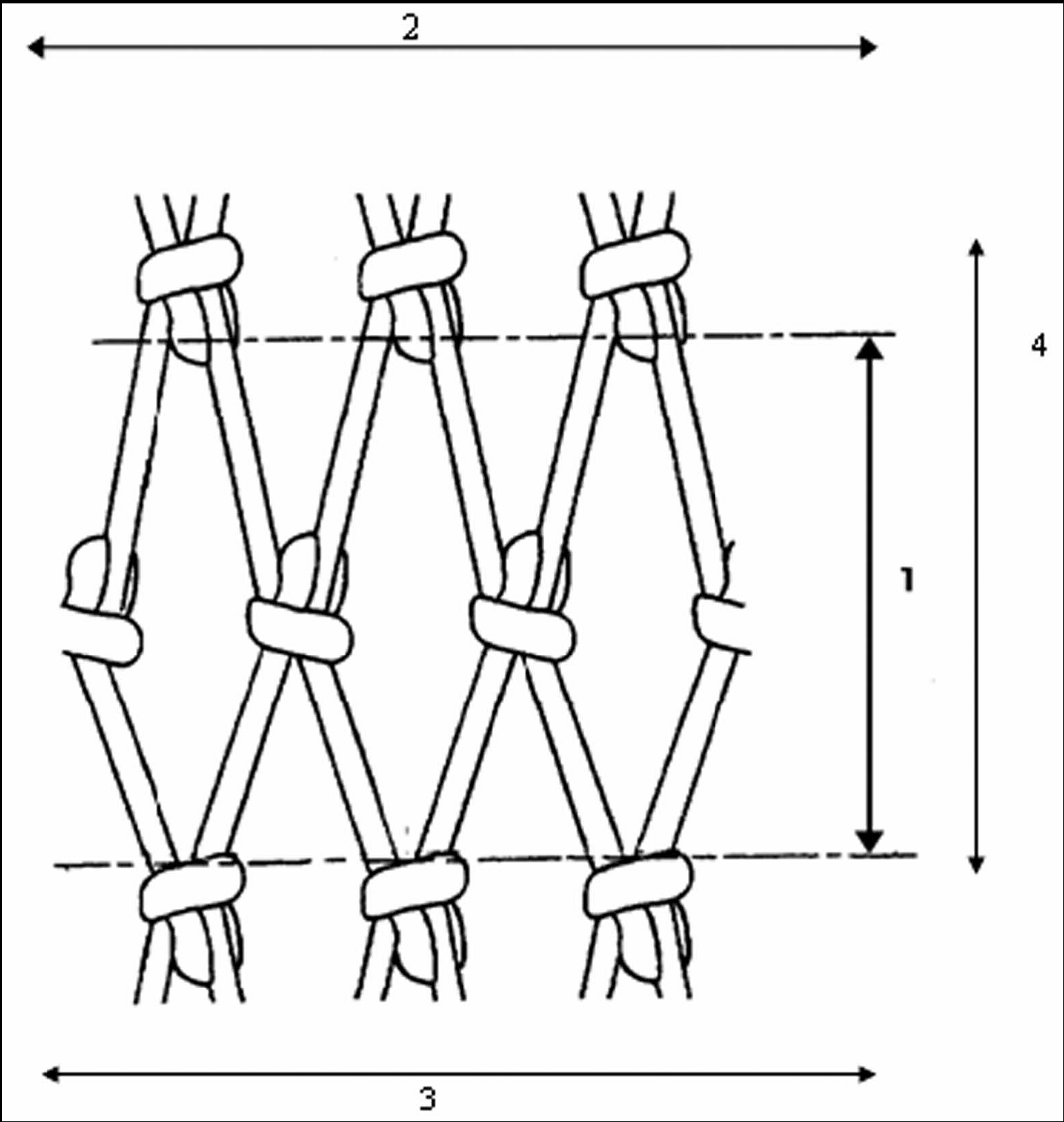
1. Size of mesh.
2. T-direction.
3. General course
of the netting.
4. N-direction.
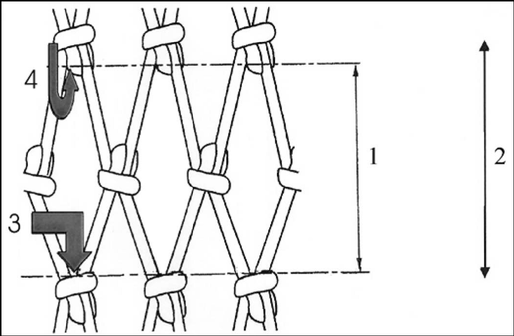
Schedule 7[38]
(Regulation 27)
Diamond knotted netting and
T90 netting
Figure
1
The direction of
run of the netting twine in a standard diamond knotted net (A) and in a net
turned 90° (B) is shown below.
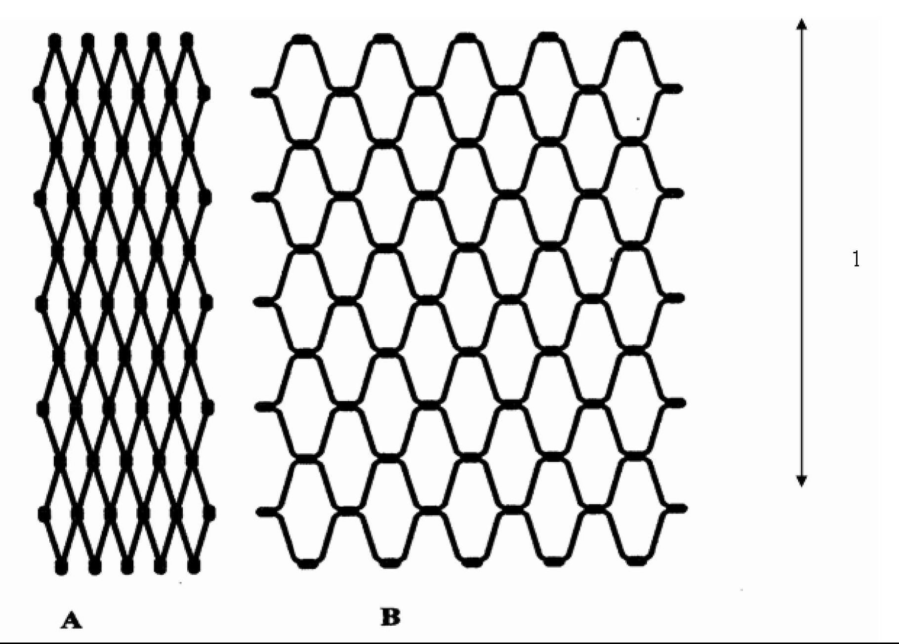
A. Standard
diamond mesh netting.
B. T90 mesh netting.
1. longitudinal
axis of the net.
Longitudinal axis of the
net
Figure
2
Schedule 8[39]
(Regulation 28)
Technical specificationS of
the mesh gauge
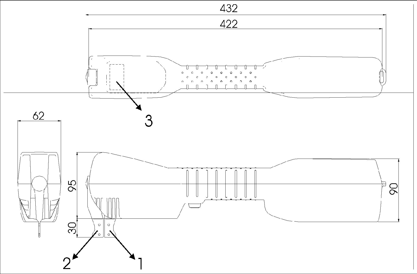
1. The
mesh gauge must –
(a) automatically apply a longitudinal measuring
force when measuring the mesh size of fishing nets;
(b) have
2 jaws, 1 fixed and 1 movable, each 2 mm thick with rounded
edges with a radius of 1 mm to ensure that the jaws slip easily over the twine
as shown in the figure below;
(c) be
electrically driven or, if battery powered, must be capable of making
1,000 consecutive mesh measurements before requiring to be recharged;
(d) be
able to apply selected longitudinal forces, in the range 5 to 180 N,
to the meshes with a precision of 1 N;
(e) have
a built-in system for measuring the applied force;
(f) be
capable of stretching a mesh at a constant speed of
300 ± 30 mm/min by the movable jaw;
(g) be
able to measure meshes from 10 to 300 mm and have detachable jaws for use
on small and large meshes;
(h) have
a measurement precision of 1 mm;
(i) have
a structure that is rigid and will not distort under load;
(j) be
light yet robust and must not weigh more than 2.5 kg;
(k) be
made of materials resistant to corrosion under marine conditions;
(l) be
water resistant and unaffected by dust to standard IP56(*);
(m) be stable
in operation over a temperature range of
–10° to +45°C;
(n) be
able to withstand temperatures between –30° and +70°C during storage and transportation;
(o) be
controlled by software that must provide a menu of functions and enable the
gauge to self-test the electronic and mechanical parts when started;
(p) have
a display that shows that the gauge is ready for use and, if it is not, display
an error message and then close down and cease operating;
(q) be
capable of operating with 1 hand and have functions that can be accessed
via external buttons;
(r) show
data on an integral display and present each measurement, the number of
measurements made in a series, and the mean value in millimetres;
(s) be
capable of storing the data of at least 1,000 measurements in its memory
and be capable of transmitting data to a computer;
(t) contain
a function to calculate the mean mesh size rounded to the nearest 0.1 mm;
(u) incorporate
software that has a function that automatically selects the largest diagonal of
each mesh to calculate the mean mesh size of square mesh netting;
(v) be
capable of saving the data of all measurements made; and
(w) be marked with the words “EC gauge”.
2. Some
netting creeps under load. The gauge must be capable of responding to this
condition by reapplying the fixed force, requiring an algorithm in the
controlling software, as described in the Appendix.
____________________
(*) Internal
protection (IP) codes are specified in the international standard of the
International Electrotechnical Commission (IEC) 60529.
Figure
(These drawings are for
illustrative purposes only)
|
Description
|
|
1
2
3
|
Fixed jaw with
load cell
Movable jaw
Display
|
|
Specifications
|
|
Length measurement
Range:
Accuracy:
Force
measurement
Range:
Precision:
Fixed measuring
forces:
Speed movable
jaw:
Battery
autonomy:
Data storage
Memory:
Temperature
range
Operating:
Storage:
Waterproof
Shockproof
Weight
|
10-300 mm
± 1 mm
5-180 N
± 1 N
10 N, 20 N, 50 N, 125 N
300 ± 30 mm/min(*)
minimum 1,000
measurements
minimum 1,000
measurements
– 10°
to +45°C
– 30°
to +70°C
to standard IP56
maximum
2.5 kg
|
|
(*) Speed of the
movable jaw during the stretching of the mesh. The unloaded speed of the
movable jaw can be higher.
|
Appendix to Schedule 8
Measurement algorithm
To allow for creep in a
stretched mesh –
1. extend
the movable jaw into the mesh at a constant speed of
300 ± 30 mm/min (*), until the measurement force is
reached;
2. stop
the motor and wait for 1 second;
3. if
the force drops below 80% of the pre-set measurement force, extend the movable
jaw into the mesh until the measurement force is reached once more.
____________________
(*) Speed
of the movable jaw during the stretching of the mesh. The unloaded speed of the
movable jaw can be higher.
Schedule 9[40]
(Regulation 28)
Technical specification of
the twine thickness gauge
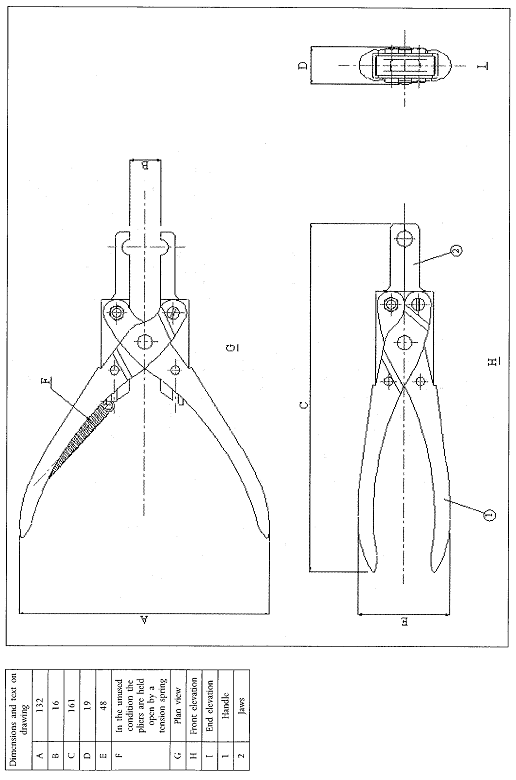
Gauges for assessing the
thickness of twine must –
(a) be made of durable, non-corrosive material
able to withstand a harsh marine environment and must be manufactured in
accordance with the drawings shown in the figure below;
(b) have
edges around the circumference of each side of the circular hole for assessing
the thickness of the twine (the hole) rounded to avoid abrasion when the twine
is pulled through the hole to test legality;
(c) be
constructed with the nose of the pliers rounded to facilitate inserting the
jaws between double twines;
(d) have
jaws with parallel action that are sufficiently strong to prevent deformation
of the jaws during any reasonable use, bearing in mind that the jaws have to be
squeezed closed with manual force during every measurement;
(e) have
the inside faces of the jaws milled to leave a 0.5 mm gap for a distance
of 1 mm either side of the hole when the jaws are closed in order to avoid
single filaments of material protruding from braided or twisted construction
being trapped in the flat surfaces of the jaws on each side of the hole in
which the twine is seated;
(f) have,
when the jaws are closed, the diameter of the circular hole marked in
millimetres on one of the jaws, adjacent to the hole; the jaws are closed when
the surface of both internal sides of the jaws touch each other and are flush;
(g) have
a tolerance for the hole diameter of 0 + 0.1 mm;
(h) be
conveniently portable such that a set of 4 (4 mm, 5 mm,
6 mm, and 8 mm) gauges may be carried by a fishery officer during
vessel to vessel transfer at sea;
(i) if
gauges are of different sizes, be easily identifiable;
(j) be
easy to insert between double twine. After the gauge has been inserted into
position, it must be capable of easy operation with 1 hand;
(k) be
marked with the words “EC gauge”.
Figure
Twine-measuring pliers
assembly
Schedule 10[41]
(Regulations 29 and 30)
Calibration and testing of
the mesh gauge
A. Verification
of length measurement
The verification of length
measurement must be performed by inserting the jaws of the gauge to be used
during the inspection, into slots of different lengths in the calibrated rigid
test plate. This can be done at any time.
Figure 1
Length of slots in mm
B. Verification
of force measurement
The verification of force
measurement must be performed by hanging calibrated weights on the fixed jaw
containing the load cell, with the gauge held vertical and secure. The weights
must have the following values: 10, 20, 50 and 125 N. The weights must
only be used under stable conditions.
Figure 2
(This drawing is for
illustrative purposes only)
1. Test weight
Schedule 11[42]
(Regulations 33 and 35)
Preparation of the mesh
gauge
1. The
fishery officer must –
(a) select the appropriate size of jaw for the
meshes to be measured;
(b) ensure
that the jaws are clean;
(c) check
that the gauge completes the self-test satisfactorily;
(d) select
the measuring force to be applied as follows –
(i) for
mobile gear –
20 N for mesh sizes
< 35 mm,
50 N for mesh sizes
≥ 35 mm and < 55 mm,
125 N for mesh sizes
≥ 55 mm;
(ii) for
passive gear –
10 N for all mesh sizes;
(e) verify
the jaw type setting. The default setting is ‘Normal’. If small or
large jaws are used, the fishery officer must enter the menu and change the jaw
type setting accordingly.
2. When
the activities set out in paragraph 1 are completed the gauge is ready to
undertake mesh measurements.
Schedule 12[43]
(Regulations 33 and 34)
Operation of the mesh gauge
for inspection
When measuring the meshes
the fishery officer must –
(a) insert the jaws into the mesh opening with
the fixed jaw of the gauge against the knot, as shown in the figure below;
(b) activate
the gauge allowing the jaws to open until the movable jaw reaches the opposite
knot and stops when the set force is reached:
Figure
1. Mesh size.
2. N-direction.
3. Fixed jaw.
4. Movable jaw.
Schedule 13[44]
(Regulations 35, 37D and 37E)
Twines in diamond and
square mesh netting
Figure