
Weights and
Measures (General Provisions) (Jersey) Order 1968[1]
PART 1
GENERAL
Interpretation
1
(1) In
this Order, unless the context otherwise requires –
“automatic weighing
machine” means a machine in which special self‑acting machinery is
introduced to effect an automatic feed, the rapid weighing of given loads, the
registration and summation of loads, and other similar purposes or some of
them;
“beam scale”
means any equal-armed weighing instrument, the pans of which are below the
beam;
“capacity”
means, in relation to a weighing instrument, the maximum load which the
instrument is constructed to weigh;
“counter machine”
means any equal-armed weighing instrument of a capacity not exceeding one
hundredweight, the pans of which are above the beam, and includes, together
with the ordinary type, such instruments as are specially designed for counter
use, and which do not exceed the said capacity;
“dead-weight machine”
means any weighing instrument similar in principle of construction to a counter
machine but of a capacity of one hundredweight or more, and
includes –
(a) such an instrument with
the weighing platform near the ground and with connecting stays or hooks above
the beam and commonly known as a low pattern machine or sack scale;
(b) such an instrument with
the weighing platform at any convenient height and with the connecting stays or
hooks below the beam, and commonly known as a single machine or scoop scale;
“error” in
relation to a weighing instrument, includes deficiency in sensitiveness;
“Law” means
the Weights and
Measures (Jersey) Law 1967;
“prescribed limits
of error” means the limits of error prescribed by this Order;
“prescribed stamp”
means the stamp prescribed by the Weights and Measures
(Prescribed Stamp) (Jersey) Order 1975;
“weighing instrument”
means any weighing instrument other than a weight or counterpoise.
(2) References
in this Order to any enactment shall be construed as references to that
enactment as amended by any subsequent enactment or to any other enactment
repealing and re-enacting that enactment with or without further amendment.
Application
2
(1) Subject
to the provisions of paragraph (2), the provisions of this Order shall
apply to all weighing and measuring equipment for use for trade of the
following classes –
(a) linear measures;
(b) liquid capacity
measures;
(c) beam scales;
(d) balances;
(e) counter machines;
(f) spring balances;
(g) steelyards;
(h) dead-weight machines;
(i) platform weighing
machines;
(j) weighbridges;
(k) crane weighing
machines;
(l) automatic
weighing machines;
and such equipment is
hereby prescribed for the purposes of Article 12(1) of the Law.
(2) Nothing
in this Order shall apply to any weighing or measuring equipment of the
following descriptions –
(a) weighing equipment for
the use by the public for weighing a person;
(b) weighing equipment for
use only for weighing coins or currency notes for the purpose of determining
their number.
Inspection and testing of weighing and measuring equipment for use
for trade
3
Weighing and measuring
equipment shall be submitted for testing and shall be tested in a clean
condition.
4
Weighing or measuring
equipment submitted for testing shall be complete in itself, and shall not bear
a maker’s mark or any trade mark, which, in the opinion of the inspector,
might reasonably be mistaken for the prescribed stamp.
Passing as fit for use for trade
5
No weighing or measuring
equipment shall be passed as fit for use for trade unless –
(a) subject to the
provisions of paragraph (2), it complies with the appropriate requirements
of this Order;
(b) in the case
of –
(i) weighing
or measuring equipment presenting any novel feature,
(ii) a
weighing instrument with removable hooks, (other than the hooks at the end of
the steelyard indicators on weighing instruments constructed on the compound
lever principle),
(iii) a
counter machine with sliding counterpoises,
(iv) a price
computing weighing instrument,
it is of an approved
pattern;
(c) in the case of a
capacity measure, it is not marked with an indication of its purported value in
units of both the imperial system and the metric system;
(d) it is sufficiently
strong to withstand the wear and tear of ordinary use in trade.[2]
Stamping
6
(1) Subject
to the provisions of paragraph (2), no weighing or measuring equipment
shall be stamped unless it contains a plug or stud of soft metal for the
reception of the prescribed stamp, such plug or stud being made irremovable by
undercutting or otherwise.
(2) Paragraph (1)
shall not apply to –
(a) linear measures;
(b) capacity measures made
of glass, earthenware, enamelled metal, plastic or vulcanite;
(c) liquid capacity
measures made of metal;
(d) balances.[3]
Obliteration of stamps
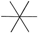
7
Stamps shall be
obliterated by an inspector, in accordance with the requirements of this Order,
by means of punches or pincers of a 6-pointed star design as shown in the
following illustration –
8[4]
(1) Subject
to paragraphs (2) to (6), an inspector shall obliterate the stamp
on –
(a) any weighing or
measuring equipment which falls outside the prescribed limits of error, or
which does not comply with any relevant requirement of this Order;
(b) any measure which has
been so broken or damaged that it cannot, in the inspector’s opinion be
properly adjusted or the accuracy of which has, in the inspector’s
opinion, been affected by an alteration, adjustment, addition or repair made or
carried out since it was last stamped;
(c) any equal armed
weighing instrument which has been altered, adjusted or repaired since it was
last stamped; or
(d) any other weighing
instrument which has been so altered, adjusted or repaired since it was last
stamped that it is in the inspector’s opinion, necessary to ascertain
that the indications of the instrument remain correct throughout its range.
(2) Nothing
in paragraph (1)(c) or (d) shall require an inspector to obliterate the
stamp on any weighing instrument which has been altered or adjusted if the
inspector is satisfied –
(a) that the purpose of the
alteration or adjustment was to modify an imperial instrument to indicate
weight in metric units and involved only the replacement or addition of a dial,
chart or pointer; and
(b)
(i) that within the
period of 15 days following the making of the alteration or adjustment the
requirements of paragraph (5) were complied with, or
(ii) that
the period of complying with those requirements has not yet expired.
(3) Where
any equipment is found not to comply with the requirements of this Order solely
because it falls outside the prescribed limits of error, an inspector may,
instead of immediately obliterating the stamp thereon pursuant to paragraph (1),
serve upon the person in possession of the equipment a notice requiring the person
to ensure that the equipment is brought within the prescribed limits of error
before the expiry of 28 days, or such shorter period as may be specified in the
notice.
(4) Where
any notice given pursuant to paragraph (3) is not duly complied with the
inspector shall obliterate the stamp on the relevant equipment.
(5) The
requirements referred to in paragraph (2)(b) are that the chief inspector
of weights and measures is furnished by the person carrying out the alteration
or adjustment with the following particulars, namely –
(a) the person’s
name and address;
(b) particulars
by which the instrument may be identified;
(c) the
name of the user and the address at which the instrument will be available for
inspection;
(d) an
indication as to whether or not the modification consisted only of the addition
or replacement of a chart, dial or pointer; and
(e) where
there is any other form of modification in place of or in addition to that in sub-paragraph (d),
an indication as to whether the person owning the instrument and the person
modifying it have agreed that its accuracy after modification shall be such
that it falls within the limits ordinarily applicable upon the testing of such
an instrument with a view to its being passed as fit for use for trade.
(6) Where
the alteration or adjustment of an instrument for the purpose of modifying it
to indicate weight in metric units involves the carrying out of 2 or more
operations and the instrument is used, or intended to be used, for trade
between the carrying out of those operations, each such operation shall be
treated for the purposes of paragraph (2) as a separate alteration or
adjustment.
PART 2
LINEAR MEASURES
Materials and principles of construction
9
(1) Linear
measures shall be made of steel, brass, aluminium alloys, ivory, laminated
bakelite, reinforced fibreglass, hard wood or woven tape, or of any other
material approved by the Minister.
(2) Linear
measures of a maximum purported value of 2 feet or more and made of wood shall
have both ends tipped with metal and the tips shall be riveted through the
wood.
10
(1) Linear
measures shall be straight and free from flaws.
(2) In
the case of measures with sliding or calliper arms, such arms shall have no
more play than is necessary for easy movement.
11
(1) Linear
measures which are subdivided shall be graduated clearly and indelibly and the
numbered graduations shall be marked by longer lines than the graduations which
are not numbered.
(2) Linear
measures which are not subdivided shall be clearly and indelibly marked with
the words “not subdivided”.
(3) Linear
measures shall have their maximum purported value conspicuously, legibly and
durably marked at one end of the measure, either in full or by means of one of
the following abbreviations only –
Testing
12
Linked measures and
riband or tape measures shall be tested when subjected to a tension or pull as
follows –
|
(a)
|
riband or tape measures made of
material other than metal
…………….................
|
2 pounds;
|
|
(b)
|
riband or tape measures made of
metal
|
10 pounds;
|
|
(c)
|
linked measures
……………………........
|
15 pounds;
|
and the measure under
test shall be supported throughout its whole length on a plane and even base.
13
Part 1 of Schedule 1
shall have effect for prescribing limits of error in relation to linear
measures.
Stamping
14
(1) Subject
to the provisions of paragraph (2), linear measures shall be stamped near
one end or, in the case of sub-divided measures near the beginning of the scale
on each graduated side.
(2) In
the case of linked measures and riband and tape measures, the stamp may be
placed on a metal label or disc permanently attached to the measure, or on the
handle thereof.
PART 3
LIQUID CAPACITY MEASURES
Materials and principles of construction
15
Liquid capacity measures
shall be made of aluminium alloys, copper, copper alloys, earthenware,
enamelled-metal, glass, nickel alloys, plated, tinned or galvanised iron or
steel, stainless steel, tin alloys, urea formaldehyde plastic or vulcanite, or
of any other material approved by the Minister.
16
(1) Liquid
capacity measures made of pewter or of other tin alloys shall contain at least
80% by weight of tin, and shall not contain more than 10% by weight of lead.
(2) Every
such measure shall bear the name and address of the maker on the underside of
the bottom of the measure.
17
(1) Liquid
capacity measures made of copper or copper alloys shall be well tinned all over
the inside and, on plated measures, the coating shall show no signs of peeling.
(2) On
measures on which there are strengthening ribs or bands, such ribs or bands
shall not take such a form as to show, by indentation or otherwise, any
divisions on the measure which, in the opinion of the inspector, might
reasonably be mistaken for graduations.
18
Liquid capacity measures,
if their maximum purported values are clearly defined, may have a top rim, lip
or retaining edge to prevent spilling:
Provided
that –
(a) in
the case of measures made of metal for the sale of milk and in the form of
churns, the top rim, lip or retaining edge shall not increase the capacity of
the measure by more than 25% of its maximum purported value;
(b) in
the case of other measures, the top rim, lip or retaining edge shall not
increase the capacity of the measure by more than 10% of its maximum purported
value.
19
No liquid capacity
measure shall be so constructed that –
(a) it
has a false bottom; or
(b) it
does not completely empty when tilted to an angle of 120° from the
vertical.
20
In the case of liquid
capacity measures fitted with a tap, the tap shall completely empty the measure
without tilting.
21
Subject to the provisions
of Article 26, liquid capacity measures made of metal, glass or
earthenware which are intended for use as drinking vessels may be provided with
a spout or projecting mouth and may also have a bottom rim but, in the case of
measures of a maximum purported value not exceeding one pint, such rim shall
not project more than half an inch below the bottom of the measure.
22
Subject to the provisions
of Article 26, liquid capacity measures made of glass shall have their
maximum purported values defined either –
(a) by
the brim of the measure; or
(b) by
a line not less than 2 inches in length and distant not less than half an inch
nor more than one and a half inches from the brim.
23
Liquid capacity measures
made of earthenware shall have their maximum purported values defined
either –
(a) by
the brim of the measure; or
(b) by
an indelible line marked on the inside of the measure, so that –
(i) in
the case of measures of a maximum purported value not exceeding one quart, the
distance from the bottom of the line to the brim does not exceed 3/8 of an
inch,
(ii) in
the case of measures of other maximum purported values, the said distance does
not exceed 3/4 of an inch.
24
(1) Subject
to the provisions of paragraphs (2) and (3) of this Article and of Article 26(d),
any liquid capacity measure (other than a measure made of metal of a maximum
purported value of half a gallon or less or 2½ litres or less) may be
used for trade by means of any division or subdivision marked thereon as a
capacity measure of any lesser quantity.
(2) In
the case of measures made of glass which are subdivided by graduations, the
total number of graduations on the measure shall be marked thereon and all
graduations shall be marked by clearly defined lines, which shall –
(a) in
the case of measures of a maximum purported value of one gallon or less, be not
less than one inch in length; and
(b) be
not less than 1/12 of an inch apart.
(3) In
the case of measures made of metal which are subdivided by graduations, all
graduations shall be marked by clearly defined lines and if such measures
are –
(a) of a
maximum purported value not exceeding 5 gallons, the graduations shall be
marked on 2 metal strips fixed opposite to each other inside the measure; or
(b) of a
maximum purported value exceeding 5 gallons, the graduations shall be marked
either on a metal strip inside the measure and extending to the whole depth of
the measure or on metal tablets securely soldered inside the measure.
25
(1) Liquid
capacity measures shall have their maximum purported values conspicuously,
legibly and durably marked on the outside of the body of the measure (and not
on the handle, rim or edges) either in full or by means of one of the following
abbreviations only –
|
gal
|
qt
|
pt
|
fl
|
oz
|
fl
|
dr
|
min
|
l
|
dl
|
cl
|
ml.
|
(2) The
maximum purported value shall be marked –
(a) on
measures made of glass on which the said value is defined by a line, at the
line, immediately below the line or on the base;
(b) on
measures made of enamelled-metal, in a distinctly different colour from that of
the body of the measure;
(c) on
measures made of metal, and of a said value exceeding 5 gallons, on the
graduated strip or the topmost tablet as well as on the outside of the measure;
(d) on
measures made of sheet metal, by means of embossing, engraving or impressing on
the body of the measure or on a slip of tin or on a shield securely soldered to
the measure.
26
Liquid capacity measures
of a maximum purported value not exceeding  gill or
50 millilitres for use for the sale of intoxicating liquor shall be made of
glass, transparent plastic or stainless steel and shall –
gill or
50 millilitres for use for the sale of intoxicating liquor shall be made of
glass, transparent plastic or stainless steel and shall –
(a) be
of the conical or cylindrical type;
(b) have
the maximum purported value defined –
(i) by
the brim of the measure, or
(ii) by a
line, distant not less than ½ an inch nor more than ¾ of an inch
from the brim, which encompasses the circumference of the measure;
(c) in
the case of measures of a maximum purported value of  gill or
25 millilitres, be unsubdivided;
gill or
25 millilitres, be unsubdivided;
(d) in
the case of measures of a maximum purported value of gill or
50 millilitres, be unsubdivided, or subdivided to indicate gill or
25 millilitres only, by a line which encompasses the circumference of the
measure.[5]
Testing
27
(1) Liquid
capacity measures of maximum purported values between  gill
and 8 gallons, inclusive, shall be tested by transferring water from the Jersey
standard or the working standard into the measure under test.
gill
and 8 gallons, inclusive, shall be tested by transferring water from the Jersey
standard or the working standard into the measure under test.
(2) Measures –
(a) with
a lip or rim, shall be tested to the bottom of the lip or rim;
(b) on
which the purported value is defined by a line, shall be tested to the bottom
of the line and, in the case of measures made of glass, shall be so tested by
taking the level of the water at the bottom of the meniscus.
28
Part 2 of Schedule 1
shall have effect for prescribing limits of error in relation to liquid
capacity measures.
Stamping
29
The stamp shall be placed
on liquid capacity measures as follows –
(a) on
measures made of glass, transparent plastic, earthenware, enamelled-metal, urea
formaldehyde plastic or vulcanite, it shall be etched, sand-blasted or
otherwise permanently marked beneath or near to the indication of the purported
value on the outside of the measure;
(b) on
measures made of metal (other than enamelled-metal) which are subdivided, it
shall be placed both on solder affixed to the inside strips or tablets near to
the topmost graduation and on the outside of the measure near to the indication
of the purported value;
(c) on
measures made of metal which are not subdivided and which have no lip or rim,
it shall be placed near to the indication of the purported value on the outside
of the measure;
(d) on
measures made of metal (other than enamelled-metal) which are not subdivided
but which have a lip or rim, it shall, as far as practicable, be placed on the
bottom of the inside of the lip or rim;
(e) on
measures other than those specified in paragraphs (a) to (d), it shall be
placed on a plug or stud of soft metal provided for such use. [6]
PART 4
ALL WEIGHING INSTRUMENTS
Application of this Part
30
Notwithstanding anything
contained in Parts 5 to 12 relating to weighing instruments of a
particular type, class or description, the provisions of this Part of this Order
shall have effect in relation to all weighing instruments to which this Order
applies.
Provisions as to marking
31
(1) New
weighing instruments shall have their maker’s name and their capacity
conspicuously, legibly and durably marked thereon.
(2) Where
units of measurement are marked on weighing instruments, they shall be marked
either in full or by means of one of the following abbreviations
only –
|
cwt
|
ctl
|
qr
|
lb oz
|
dr
|
gr
|
oz.tr
|
|
kg
|
kilogram
|
kilog
|
g
|
gram
|
grm
|
|
mg
|
milligram
|
C.M.
|
|
|
|
Materials and principles of construction
32
(1) All
knife-edges and bearings in weighing instruments shall be made of hard steel or
agate, or of other material approved by the Minister and they shall be so
fitted as to allow the beam or steelyard indicator to move easily.
(2) All
knife-edges in weighing instruments shall substantially bear on the whole
length of their working parts.
33
(1) All
removable counterpoises weighing one ounce or more and all sliding poises on
weighing instruments shall contain an undercut adjusting hole or other means of
adjustment.
(2) Any
loose material used in any such counterpoise or poise shall be securely
enclosed therein.
34
Weighing instruments with
removable parts the removal of which would affect their accuracy, shall be so
constructed that they cannot be used if any of the said parts are removed.
35
Where weighing
instruments have interchangeable or reversible parts, the interchange or
reversal thereof shall not affect the accuracy of the instrument.
36
All graduations on
weighing instruments shall be so defined that the positions of all sliding
poises or indicators are clearly readable.
Testing
37
(1) Subject
to the provisions of paragraph (2), in testing any weighing instrument, an
inspector shall satisfy himself or herself that –
(a) it is
properly balanced when unloaded;
(b) the
beam (if any) has sufficient room for oscillation and returns to the position
of equilibrium when the load is removed;
(c) the
indicator (if any) returns to the zero mark or minimum graduation when the load
is removed.
(2) Paragraph (1)(a)
shall not apply in the case of a weighing instrument which is of an approved
pattern, if such an instrument is not so constructed as to balance when
unloaded.
38
Movable weighing
instruments provided with a base shall be tested on a level plane.
39
Weighing instruments
which are designed to be suspended when in use shall be suspended during
testing.
40
(1) Weighing
instruments used in any of the following transactions, that is to say,
transactions –
(a) in
gold, silver or other precious metals;
(b) in
precious stones;
(c) in
jewellery;
(d) in
silk;
(e) by
retail, in drugs or other pharmaceutical products:
shall either –
(i) be balances, or
(ii) being
instruments other than balances, fall within the prescribed limits of error
specified in Part 2 of Schedule 2 for beam scales marked “Class
B”.
(2) Weighing
instruments used in retail transactions in tobacco shall either –
(a) be
balances; or
(b) being
instruments other than balances, fall within the prescribed limits of error
specified in Part 2 of Schedule 2 for beam scales marked “Class
B” or “Class C”.
41
(1) Unless
otherwise provided in this Order, vibrating weighing instruments shall be
tested for sensitiveness by loading the instrument with the maximum testing
load (or as near thereto as, in the opinion of the inspector, circumstances
permit) with the beam or steelyard indicator in a horizontal position, and
ascertaining that it moves with the addition of the weight to be added to test
sensitiveness as specified in Parts 2, 3, 5, 6, 7, 9 or 10, as the case
may be, of Schedule 2, and no test for sensitiveness at a lower load shall
be made.
(2) In
the case of beam scales and balances, the addition of the said weight to either
pan shall cause an appreciable movement of the beam.
(3) In
the case of vibrating weighing instruments other than beam scales or balances,
the addition of the said weight shall cause the beam or steelyard indicator to
rise or to fall to the limit of its range of movement.
42
Vibrating weighing
instruments shall be tested for error by ascertaining the weight to be added
thereto or removed therefrom in order to bring the beam or steelyard indicator
of the instrument to a horizontal position when the instrument is loaded with
the maximum testing load (or as near thereto as, in the opinion of the
inspector, circumstances permit).
43
Accelerating weighing
instruments shall be tested for error by ascertaining the weight required just
to keep the beam or steelyard indicator in a horizontal position on its stop or
carrier and no more, and shall be further tested by ascertaining the weight
required to bring back the beam or steelyard indicator from its position of
greatest displacement to the horizontal position, the instrument being at all
times fully loaded and truly balanced.
44
In testing weighing
instruments fitted with a price computing mechanism, an inspector shall, in
addition to testing at each numbered graduation, satisfy himself or herself
that –
(a) they
indicate the price correctly; and
(b) they
comply with the requirements of this Order in so far as they are applicable to
the particular type, class or description of weighing instrument concerned.
PART 5
BEAM SCALES AND BALANCES
Principles of construction
45
No beam scale
shall –
(a) be
fitted with loaded weight pans;
(b) if
of a capacity of less than 2 hundredweight, be fitted with wooden scale boards.
46
(1) Any
attachment for adjusting beam scales or balances shall be permanently affixed
to the instrument and shall be so constructed that it cannot be readily
tampered with.
(2) All
beam scales with wooden scale boards shall be provided with an adjusting
balance ball or box.
47
All beam scales shall be
indelibly marked either with the inscription “Class B” or with the
inscription “Class C”.
Testing
48
(1) In
testing beam scales and balances, an inspector shall satisfy himself or herself
that, when the pans are loaded to half the capacity of the instrument and the
knife-edges or bearings are moved laterally or backwards and forwards within
their limits of movement, there is no appreciable difference in the indications
of weight shown by the instrument.
(2) Beam
scales and balances shall fall within the prescribed limits of error whether
the load is on the middle or near the edges of the pans.
49
Parts 1 and 2 of Schedule 2
shall have effect for prescribing limits of error in relation to beam scales
and balances.
Stamping
50
(1) In
the case of beam scales, the stamp shall be placed on a plug or stud provided
for that purpose.
(2) In
the case of balances, the stamp shall be placed either –
(a) on
the plug or stud on the base of the pillar; or
(b) on a
special plate permanently and irremovably attached to the base of the
instrument.
PART 6
COUNTER MACHINES
Materials and principles of construction
51
Counter machines shall not
be constructed on the accelerating weighing instrument principle.
52
(1) Where
the beam of a counter machine has 2 side members, they shall be connected
together by not less than 2 cross bars, and the supports for the pans of such
machines shall be of suitably rigid structure, such as crosses strengthened by
straps.
(2) The
centre forks of counter machines shall be so fixed that they cannot twist or
get out of place.
53
The bearing surfaces and
points of contact of all stays, hooks and loops of counter machines shall be of
hard steel or agate, or of other material approved by the Minister.
54
(1) Where
a counter machine is adjusted by means of a balancing box, the box shall be
permanently fixed beneath the weights pan and shall only be large enough to
contain loose material to an amount not exceeding 1% of the capacity of the
machine.
(2) No
other means of adjustment shall be fitted, except where the machine is of an
approved pattern.
Testing
55
(1) In
testing counter machines, an inspector shall satisfy himself or herself –
(a) in
the case of non-self indicating machines, that the minimum movement of the beam
from the horizontal in either direction is as follows –
|
Capacity of machine
|
Minimum movement of beam from
the horizontal
|
|
Not exceeding 4 pounds.....................................
|
¼ inch
|
|
Above 4 pounds and not exceeding
7 pounds
|
 ” ”
|
|
„ 7 „
„
„
„
28
„
|
 ” ”
|
|
„ 28 „
„
„
„
56
„
|
 ” ”
|
|
„ 56 „ .....................................................
|
½ ”
|
;
|
(b) that, when the pans are loaded to half the
capacity of the machine (the load being uniformly distributed) and the
knife-edges or bearings are moved laterally or backwards and forwards within
their limits of movement, there is no appreciable difference in the indications
of weight shown by the instrument.
(2) Where
the goods pan is not in the form of a scoop, the machine shall indicate the
same weight within half the prescribed limits of error if the centre of a load
equal to half the capacity of the machine is placed on the goods pan anywhere
within a distance from the centre equal to 1/3 of the greatest length of the
pan, or, if the pan has a vertical side, against the middle of that side, the
load on the weights pan being entirely on that pan but in any position on it.
(3) Where
the goods pan is in the form of a scoop, the machine shall fall within the
prescribed limits of error when a load equal to half the capacity of the
machine is placed against the middle of the back of the scoop and a like load
is placed in any position on the scoop, the load on the weights pan being
entirely on that pan but in any position on it.
56
Parts 1 and 3 of Schedule 2
shall have effect for prescribing limits of error in relation to counter
machines.
Stamping
57
The stamp shall be placed
on a plug or stud provided for that purpose on a conspicuous part of the
counter machine.
PART 7
SPRING BALANCES
Principles of construction
58
The extremity of the
pointer of a spring balance shall not exceed 1/32 of an inch in width, and
shall not be more than 1/10 of an inch from the scale or dial.
59[7]
The distance between
successive graduations on the scale of a spring balance shall not be less than
the relevant distance specified in the following table –
|
Capacity of instrument
|
Minimum
space between graduations
|
|
(a)
|
Imperial
Scale.
|
|
|
Not more than 30 lb
……………………..
|
 in. in.
|
|
Over 30 lb but not over 1 cwt
…………...
|
 in. in.
|
|
Over 1 cwt
………………………………
|
 in. in.
|
|
(b)
|
Metric
Scale.
|
|
|
Not more than 15 kg
…………………….
|
1.25 mm
|
|
Over 15 kg but not more than 50
kg
|
2 mm
|
|
Over 50 kg
………………………………
|
2.5mm
|
60[8]
Successive graduations on
the scale of a spring balance shall not indicate a difference in weight
exceeding the relevant amount specified in the following table –
|
Capacity of instrument
|
Minimum
weight corresponding to interval between successive graduations
|
|
(a)
|
As an
imperial instrument.
|
|
|
100 lb or more
………………….
|
1/200 of capacity
|
|
Under 100 lb but not less than
60 lb
|
4 oz
|
|
Under 60 lb but not less than 40
lb
|
2 oz
|
|
Under 40 lb but not less
than 20 lb
|
1 oz
|
|
Under 20 lb but not less
than 8 lb
|
8 dr
|
|
Under 8 lb but not less than 2
lb
|
4 dr
|
|
Under 2 lb but not less than 1
lb
|
2 dr
|
|
(b)
|
As a metric
instrument.
|
|
|
100 kg or more
…………………
|
1/200 of capacity
|
|
Under 100 kg but not less than
50 kg
|
200 g
|
|
Under 50 kg but not less than 30
kg
|
100 g
|
|
Under 30 kg but not less
than 20 kg
|
50 g
|
|
Under 20 kg but not less
than 6 kg
|
20 g
|
|
Under 6 kg but not less than
1½ kg
|
10 g
|
|
Under 1½ kg but not less
than 500 g
|
5 g
|
61
Where the graduations
commence at any point of the scale or dial other than at the zero indication,
the position of the pointer when there is no load shall be clearly indicated by
a zero mark.
62
Where spring balances are
provided with an adjustable pointer, the range of adjustment shall not exceed 1%
of the capacity of the instrument.
Testing
63
Spring balances shall be
tested at each numbered graduation and may also be tested at intermediate
graduations.
64
(1) Spring
balances shall be tested by means of both increasing and decreasing loads and
the spring shall be allowed to vibrate before a reading is taken.
(2) In
the case of a spring balance the pan of which is above the spring –
(a) if
the pan is not in the form of a scoop, the instrument shall indicate the same
weight within half the prescribed limits of error if the centre of a load equal
to half the capacity of the instrument is placed on the pan anywhere within a
distance from the centre equal to 1/3 of the greatest length of the pan, or, if
the pan has a vertical side, against the middle of that side;
(b) if
the pan is in the form of a scoop, the instrument shall fall within the
prescribed limits of error when a load equal to half the capacity of the
instrument is placed against the middle of the back of the scoop and again when
a like load is placed in any position on the scoop.
(3) In
the case of a spring balance the pan of which is below the spring, the
instrument shall fall within the prescribed limits of error when a load equal
to the capacity of the instrument is placed in any position on the pan.
65
Parts 1 and 4 of Schedule 2
shall have effect for prescribing limits of error in relation to spring
balances.
66
Spring balances may be
tested for efficiency or ability to recover by leaving on them, for a period
not exceeding 24 hours, a load equal to the capacity of the instrument and
then, after the expiration of a further period of 4 hours, by testing for
accuracy.
67
Spring balances shall not
be tested for sensitiveness.
Stamping
68
(1) The
stamp shall be placed on a plug or stud provided for that purpose which,
wherever practicable, shall pass through the scale or dial and the frame of the
spring balance.
(2) The
said plug or stud shall be so supported as to avoid risk of injury to the
instrument by stamping.
PART 8
STEELYARDS
Materials and principals of construction
69
Steelyards shall be made
of wrought iron or of steel, or of other material approved by the Minister.
70
In the case of every
steelyard –
(a) the
shank shall be straight;
(b) each set of notches or
graduations on the shank shall be cut in one plane and shall be at right angles
to the shank;
(c) there shall be fitted a
stop or other device to prevent excessive oscillation of the shank;
(d) end fittings, sliding
poises and suspending hooks shall not be readily removable;
(e) the sliding poise shall
be freely movable without risk of injury to the notches or graduations from
constant use, and there shall be a stop to prevent it from travelling behind
the zero mark or lowest graduation.
Testing
71
Steelyards shall be
tested at each numbered graduation by means of both increasing and decreasing
loads.
72
Parts 1 and 5 of Schedule 2
shall have effect for prescribing limits of error in relation to steelyards.
Stamping
73
The stamp shall be placed
on a plug or stud provided for that purpose on the shoulder of the steelyard.
PART 9
DEAD-WEIGHT MACHINES
Materials and principles of construction
74
(1) The
bearing surfaces and points of contact of all stays, hooks, loops and
adjustable slides on dead-weight machines shall be made of hard steel, and the
knife-edges shall be so fitted as to be incapable of twisting.
(2) Adjustable
slides on dead-weight machines shall be secured in position by means of lock
nuts or other suitably secure devices.
75
(1) The
goods platform of a dead-weight machine shall not exceed the length of the
beam, or in width double the width of the beam and folding wings shall not
increase such dimensions by more than 1/3 in either direction.
(2) The
platforms of dead-weight machines shall be made of metal or hard wood.
76
The minimum movement of
the beam from the horizontal in dead-weight machines shall be as
follows –
(a) if the machine is of
the vibrating weighing instrument type, 5/8 of an inch in both directions;
(b) if the machine is of
the accelerating weighing instrument type, 7/8 of an inch in one direction
only.
77
(1) Loose
balancing material for the adjustment of dead-weight machines shall be
contained in a balancing box permanently fixed beneath one platform and its
weight shall not exceed 0.75% of the capacity of the machine.
(2) Any
other balancing material for the adjustment of dead-weight machines shall be in
one piece and shall be permanently attached to the machine.
Testing
78
(1) Dead-weight
machines shall indicate the same weight within half the prescribed limits of error
when a load equal to one-quarter of the capacity of the machine is placed
successively at the middle of the front and back of each platform and centrally
over the knife-edges on each side of each platform.
(2) Dead-weight
machines shall also fall within the prescribed limits of error when a load
equal to the capacity of the machine is uniformly distributed over each
platform.
79
Parts 1 and 6 of Schedule 2
shall have effect for prescribing limits of error in relation to dead-weight
machines.
Stamping
80
The stamp shall be placed
on a plug or stud provided for that purpose on a conspicuous part of the beam
of the dead-weight machine.
PART 10
PLATFORM WEIGHING MACHINES AND WEIGHBRIDGES
Materials and principles of construction
81
(1) The
steelyard indicator of a platform weighing machine or weighbridge shall not
incorporate any readily removable parts, except the support for the
counterpoises.
(2) There
shall be provided on every platform weighing machine or weighbridge a stop or
stops to prevent any sliding poise from travelling behind the zero mark.
(3) The
indicating mechanism of any platform weighing machine or weighbridge may be
confined in a locked box or case, provided that the indications or graduations
are clearly visible.
82
The minimum movement from
the horizontal of the steelyard indicator of platform weighing machines and
weighbridges shall be as follows –
(a) in the case of platform
weighing machines –
(i) if
they are of the vibrating weighing instrument type, 3/8 of an inch in both
directions,
(ii) if
they are of the accelerating weighing instrument type, 5/8 of an inch in one
direction only;
(b) in the case of
weighbridges –
(i) if
they are of the vibrating weighing instrument type, half an inch in both
directions,
(ii) if
they are of the accelerating weighing instrument type, ¾ of an inch in
one direction only.
83
If a movable hutch,
barrow, frame or bucket is used instead of an ordinary platform on any platform
weighing machine or weighbridge, it shall form an essential part of the
instrument without which the instrument cannot be balanced.
84
(1) Loose
counterpoises for platform weighing machines and weighbridges shall be
identified with the instrument to which they relate by a number or other
sufficient mark of identification, which shall be indelible and they shall also
be marked with the weight which they represent, for example –
“= 1 cwt”.
(2) Loose
counterpoises which are marked in units in the imperial system shall not be of
hexagonal shape.
85
In the case of small
portable platform weighing machines for use in the weighing of coal and
commonly known as bob-up weighing machines, the counterpoises shall not be
threaded on to a pin rigidly attached to one end of the main lever, but shall
either be used in a tray or pan suspended from a knife-edge bearing or be
placed on a loose shackle.
86
The balancing arrangement
for platform weighing machines and weighbridges to compensate for daily wear
and tear shall have a range not exceeding 0.5% of the capacity of the
instrument and not less than 0.125% in each direction, and it shall be securely
attached to the instrument and actuated by a detachable key.
87
In the case of any
platform weighing machine or weighbridge which is fitted with
dials –
(a) all racks and pinions
shall be made of hard metal;
(b) the extremity of the
pointer shall not be a greater distance than 3/16 of an inch from the dial, and
shall meet but not obscure the graduations;
(c) the indicating
mechanism and any cylinders or tanks containing liquid shall be protected from
dust and from excessive variations of temperature;
(d) if the instrument is of
a type commonly known as a self-indicating pit-bank weighing machine, the
pendulous lever, suspension rod and water box shall be suitably enclosed.
88
Platform weighing
machines and weighbridges for use in weighing in units of both the imperial
system and the metric system shall bear a clear inscription to that effect.
Testing
89
Platform weighing
machines which are to be permanently fixed in the position in which they are to
be used and weighbridges, shall be tested, passed as fit for use for trade and
stamped only when completely erected ready for use and installed at the place
where they are to be used.
90
(1) In
testing platform weighing machines and weighbridges, an inspector shall where
practicable –
(a) test the instrument at
each numbered graduation up to and including one ton, or such smaller amount as
the last graduation on the steelyard indicator or dial may show;
(b) test all loose counterpoises,
if any, relating to the instrument; and
(c) either test the
instrument ton by ton, or load it with heavy material to within one ton of its
capacity and ascertain that an additional ton is correctly indicated to within
the prescribed limits of error.
(2) Platform
weighing machines and weighbridges shall indicate the same weight within half
the prescribed limits of error when a load equal to one-quarter (or as near
thereto as is practicable) of the capacity of the instrument is placed
successively in the centre and near each end or corner of the platform.
(3) Platform
weighing machines and weighbridges shall also fall within the prescribed limits
of error when a load equal to the capacity of the machine (or as near thereto
as is practicable) is uniformly distributed over the platform.
91
The following provisions
of Schedule 2 shall have effect for prescribing limits of
error –
(a) in the case of Parts 1
and 7, in relation to platform weighing machines, other than self-indicating
pit-bank weighing machines;
(b) in the case of Parts 1
and 8, in relation to self-indicating pit-bank weighing machines;
(c) in the case of Parts 1
and 9, in relation to weighbridges.
Stamping
92
(1) On
platform weighing machines and weighbridges fitted with dials, the stamp shall
be placed on a plug or stud provided for that purpose on the housing of the
instrument.
(2) On
platform weighing machines and weighbridges not fitted with dials, the stamp
shall be placed on the said plug or stud in a conspicuous position either on
the shoulder or on the opposite end of the steelyard indicator.
93
Loose counterpoises for
platform weighing machines and weighbridges shall not be stamped.
PART 11
CRANE WEIGHING MACHINES
Materials and principles of construction
94
All working parts of
crane weighing machines shall be protected from damp and dust.
95
(1) The
steelyard indicator on every crane weighing machine constructed on the lever
principle shall be rigid and may be made of special metal to resist atmospheric
influences.
(2) The
rack and pinion on every crane weighing machine fitted with dials shall be made
of hard metal.
96
The range of any
balancing or adjusting arrangement for any crane weighing machine shall not
exceed 2% of the capacity of the machine.
97
Every crane weighing
machine constructed on the hydraulic principle, in the use of which it is
necessary to twist the load hook in order to obtain a correct indication of
weight, shall have a prominent notice to that effect permanently affixed to the
machine.
Testing
98
Crane weighing machines
shall, if practicable, be tested at each numbered graduation up to the capacity
of the machine.
99
Crane weighing machines
fitted with dials shall not be tested for sensitiveness.
100
The steelyard indicator
or pointer on every crane weighing machine shall move freely, and the pointer
shall return to its initial starting point after the load has been removed.
101
Parts 1 and 10 of Schedule 2
shall have effect for prescribing limits of error in relation to crane weighing
machines.
Stamping
102
The stamp shall be placed
on a plug or stud provided for that purpose on a conspicuous part of the crane
weighing machine.
PART 12
AUTOMATIC WEIGHING MACHINES
Principles of construction
103
Subject to the provisions
of this Part, every automatic weighing machine and its integral parts shall, as
far as practicable, satisfy those requirements of this Order which are
applicable to the type, class or description of weighing instrument to which
the machine most nearly relates.
104
All beams of an automatic
weighing machine shall be identified with the machine to which they relate by
means of a number or other sufficient mark of identification, which shall be
indelible.
105
Any adjusting mechanism
on an automatic weighing machine shall be so secured and protected that it
cannot readily be tampered with.
Testing
106
(1) Subject
to the provisions of paragraph (2), every automatic weighing machine shall
be subjected to the following test (hereinafter referred to as “test
A”) that is to say –
(a) by weighing
consecutively on the machine 20 separate loads (hereinafter referred to as
“test loads”) selected for the purpose by the inspector testing the
machine and then reweighing the same loads on another weighing instrument:
Provided that, if the
inspector thinks fit, the inspector may so weigh and re-weigh more than 20
separate loads of which any 20 separate loads consecutively so weighed and
re-weighed may be treated as the test loads; or
(b) in any case where the
aforementioned testing procedure is not practicable, by directly applying to
the machine the appropriate working standard weights.
(2) In
the case of a totalising weighing machine, the provisions of paragraph (1)(a)
shall apply as if for any reference to “20 separate loads” there
were substituted a reference to “40 separate loads”, and in such
case the said test loads shall be made up as follows –
(a) 10 loads equal to the
minimum load which the machine is constructed to weigh;
(b) 10 loads each equal to
the capacity of the machine;
(c) 20 loads each equal to
the mean between the said minimum loads and the load equal to the capacity of
the machine.
107
(1) Subject
to the provisions of paragraph (3) of this Article, in the case of an automatic
weighing machine which is of an approved pattern, if, in the course of carrying
out test A in the manner specified in Article 106(1)(a), the weight of any
of the test loads exceeds the purported weight of that load by more than
½% of the said purported weight, the machine shall, when appropriate, be
subject to the further test (hereinafter referred to as “test B”)
described in paragraph (2) of this Article.
(2) For
the purposes of test B, there shall be extracted from each of those test loads
used in test A (the weight of which was found to exceed the relevant amount
specified in paragraph (1)) that single piece or item appearing to the
inspector to be the largest single piece or item in that test load, and the
machine shall then be subjected to test by re-weighing each such test load as
so modified on another weighing instrument.
(3) The
provisions of this Article shall not apply to automatic weighing machines of a
capacity of 10 pounds or more, or to automatic weighing machines for use only
for weighing solid fuel or for use only for weighing potato crisps, or to
totalising weighing machines.
108
Parts 1 and 11 of Schedule 2
shall have effect for prescribing limits of error in relation to automatic
weighing machines.
Stamping
109
The stamp shall be placed
on a plug or stud provided for that purpose on a conspicuous part of the
automatic weighing machine.
PART 13
CITATION
110
This Order may be cited
as the Weights and Measures (General Provisions) (Jersey) Order 1968.